Pareto-optimal magnetic resonance data acquisition

a magnetic resonance and data acquisition technology, applied in the direction of instruments, reradiation, measurement using nmr, etc., can solve the problem that the general understanding of the impact of k-space trajectories on mr image quality is quite limited

Active Publication Date: 2006-07-18
CASE WESTERN RESERVE UNIV
View PDF29 Cites 43 Cited by
  • Summary
  • Abstract
  • Description
  • Claims
  • Application Information

AI Technical Summary

Benefits of technology

[0012]A Pareto-optimal trajectory, designed according to the systems and methods described herein, may have non-intuitive features that are unexpected even to a trained and experienced individual entrusted to design a k-space scanning trajectory. For example, in one embodiment—designed to minimize aliasing energy (in the image domain) and acquisition time—the optimal trajectory is an unconventional single-interleaf variable-density spiral (VDS). In another embodiment—designed to minimize flow sensitivity and off-resonance blurring—the systems and methods described herein suggest a six-interleaf VDS as being Pareto-optimal. Uniform-density spirals may be close to, but not quite, Pareto-optimal in these two embodiments.

Problems solved by technology

A general understanding of the impact of k-space trajectories on MR image quality has been quite limited.

Method used


Image

  • Pareto-optimal magnetic resonance data acquisition
  • Pareto-optimal magnetic resonance data acquisition
  • Pareto-optimal magnetic resonance data acquisition

Examples


example 1

[0074]Referring now to FIG. 4, the aforedescribed method optimizes the k-space trajectory for both acquisition time and aliasing energy (in the image domain), with the goal of minimizing each. These objectives are merely exemplary and chosen for their simplicity and ease of computation.

[0075]In a first exemplary embodiment, trajectories are encoded as an (n+1)-tuple (e.g., an (n+1)-vector), wherein the first number represents the number of interleaves, followed by n real numbers, representing the spiral density (dθ / dr) for each of n annular regions of substantially equal width ranging, for example, from about 0 m−1 to about 500 m−1. The following (n+1)-tuple was used in Example 1: [1, 0.804248, 0.804248, 0.804248, 0.804248, 0.813981, 0.781736, 0.804248, 0.75656, 0.837202, 0.804248, 0.804248, 0.754025]. The first number is the number of interleaves (=1), and the remaining twelve numbers denote the spiral density dθ / dr for 12 corresponding annular regions.

[0076]The trajectory is deter...

example 2

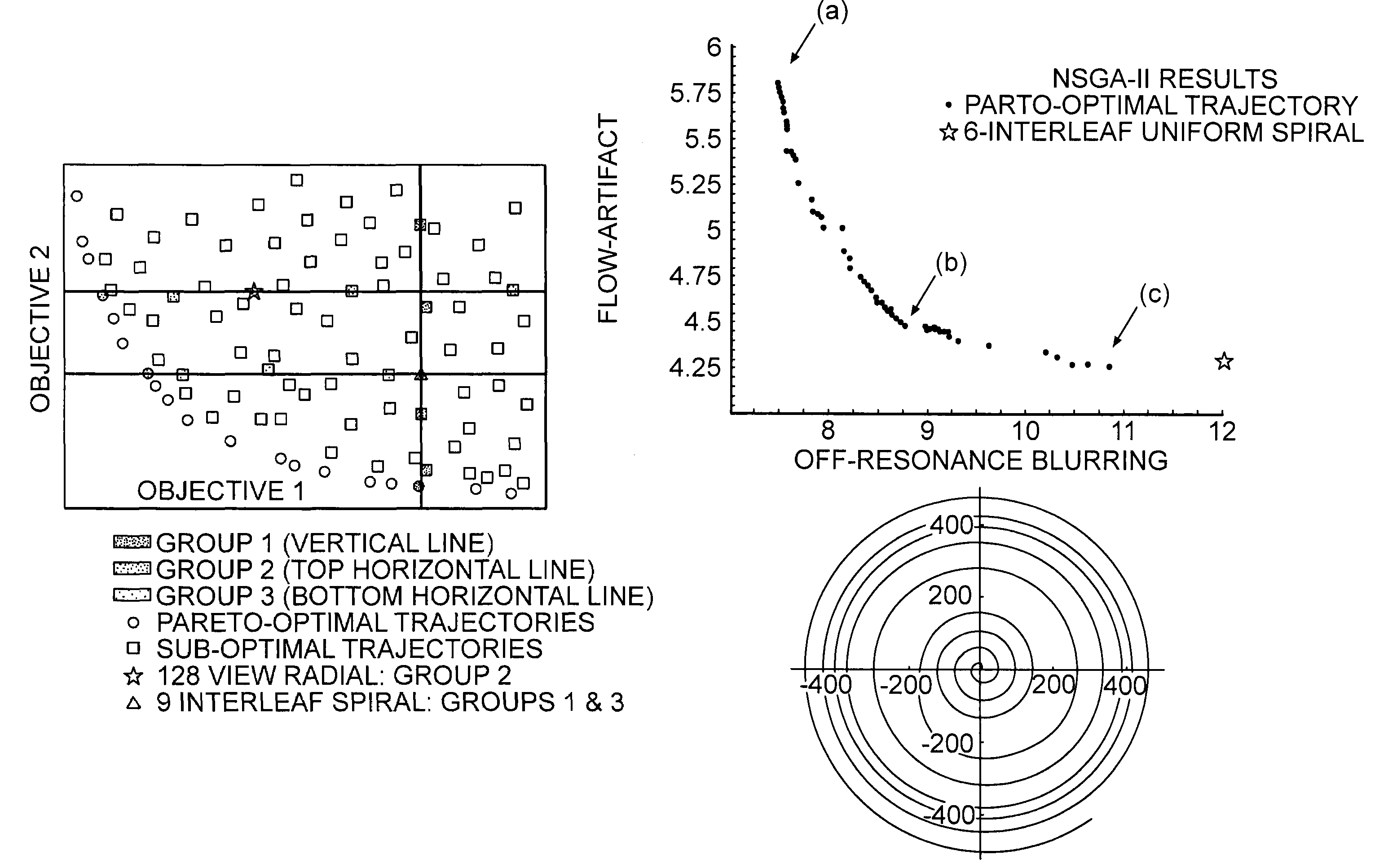
[0085]In a second example, k-space trajectory design is formulated in terms of an optimization problem aimed at minimizing off-resonance blurring while retaining the beneficial flow properties of spiral trajectories. As has been mentioned, spiral imaging is significantly less sensitive to flow artifacts, but exhibits increased sensitivity to off-resonance blurring. This may be particularly problematic in applications, such as cardiac imaging, where sharp changes in tissue susceptibility exist near the region of interest. An optimized trajectory may be expected to retain the advantageous relative insensitivity to flow, while being also less sensitive to off-resonance effects.

[0086]Off-resonance and flow-artifact energy are multi-modal, non-differentiable, and highly non-linear functions of the k-space trajectory. Most optimization techniques are unsuitable for handling such intractable, or nearly intractable, functions. The multi-objective genetic algorithms described above, however,...


PUM


Abstract

A magnetic resonance data acquisition method includes designating a plurality of parameters that are representative of conditions for acquiring data from a magnetic resonance apparatus, at least one of the parameters being variable; designating at least one objective function measuring the quality of the acquired magnetic resonance data; optimizing the at least one objective function using an optimization algorithm to find at least one set of optimum values for the parameters characterizing data acquisition; configuring the magnetic resonance apparatus with the parameters determined above, configuring by one set of the optimum values of the parameters, and instructing a magnetic resonance imaging apparatus to apply the field to the target of the data acquisition to acquire the data.

Description

CROSS REFERENCED TO RELATED APPLICATION[0001]This application incorporates by reference in entirety, and claims priority to and benefit of, the U.S. Provisional Patent Application No. 60 / 471,290, filed on 15 May 2003.BACKGROUND[0002]Magnetic Resonance Imaging (MRI) is one of the most important modern medical imaging modalities, with approximately 18 million procedures performed in 2001. MRI is currently used in three main areas: diagnostic imaging (dMRI), interventional imaging (iMRI), and quantitative imaging. Most commonly, it is used clinically for a variety of diagnostic procedures. These diagnostic procedures usually require high spatial resolution, high SNR, and low artifact levels. Additionally, it is important to have strong contrast between normal and pathological tissues. Available contrasts include: diffusion-weighted imaging for stroke; perfusion imaging for vascular tumors and infarction; spin-lattice (longitudinal) relaxation characteristic time constant T1 contrast; s...

Claims


Application Information

Patent Timeline
Patent Type & Authority Patents(United States)
IPC IPC(8): G01V3/00A61B5/055G01R33/54
CPCG01R33/54G01R33/543
Inventor DALE, BRIAN M.DUERK, JEFFREY L.LEWIN, JONATHAN S.
Owner CASE WESTERN RESERVE UNIV
Why Eureka
Try Eureka