Giant magnetoresistive element

a magnetoresistive element and giant magnet technology, applied in the field of giant magnetoresistive elements, can solve the problems of difficult to meet the requirements of a higher recording density, the probability of the entire track region becoming a dead zone, and the inability to increase the sn ratio, so as to achieve the effect of reducing the resistance of the element and high output sensitivity

Inactive Publication Date: 2006-07-18
TDK CORPARATION
View PDF12 Cites 14 Cited by
  • Summary
  • Abstract
  • Description
  • Claims
  • Application Information

AI Technical Summary

Benefits of technology

[0010]The present invention has been achieved in consideration of the problem of the use of a conventional exchange bias system, and it is an object of the present invention to provide a giant magnetoresistive element capable of securing high output sensitivity even with advances in track narrowing, and a method of manufacturing the same. Another object of the present invention is to provide a giant magnetoresistive element capable of decreasing the element resistance, and a method of manufacturing the same.

Problems solved by technology

However, with the thin free magnetic layer, Barkhausen noise, thermal fluctuation noise, and the like are increased to cause the problem that a SN ratio cannot be increased even by increasing the output sensitivity.
However, in the hard bias system, magnetization is strongly fixed at both side ends of the free magnetic layer adjacent to the permanent magnet film to produce dead zones, thereby causing the probability that the entire track region becomes a dead zone when narrowing of the track is advanced.
Therefore, it is predicted that the hard bias system using the permanent magnet film is difficult to comply with a higher recording density.
This tendency becomes remarkable as the track width dimension decreases, and thus the output sensitivity cannot be easily secured even by using the exchange bias system.
However, the use of the material having a small exchange stiffness constant undesirably decreases the Curie temperature.
Also, the selection of the material has a limitation.
Furthermore, the use of the exchange bias system has the following problem.
When the element resistance is increased, impedance is also increased to easily produce high-frequency noise, thereby failing to increase the SN ratio even with the improved output sensitivity.

Method used


Image

  • Giant magnetoresistive element
  • Giant magnetoresistive element
  • Giant magnetoresistive element

Examples


Embodiment Construction

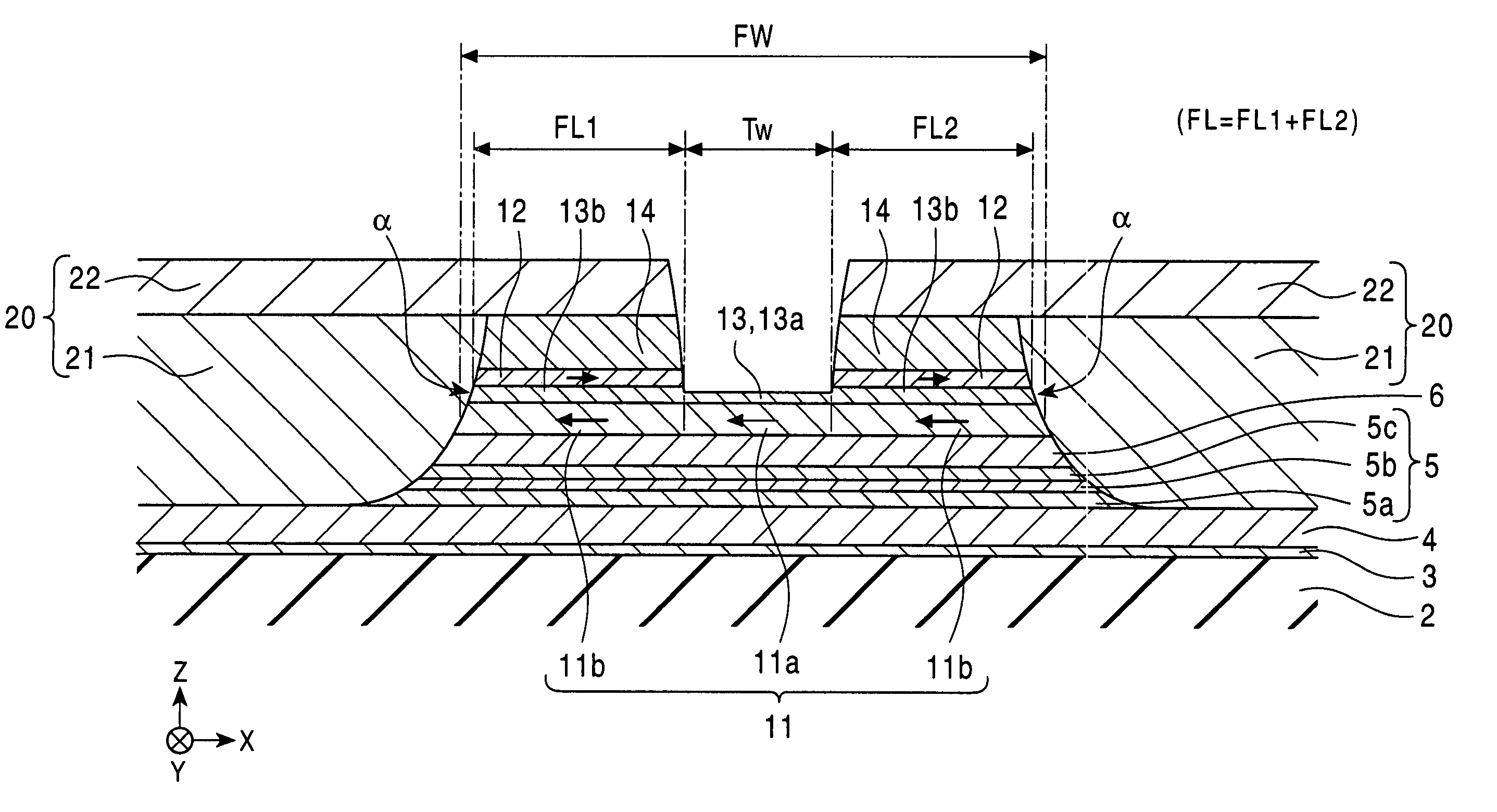
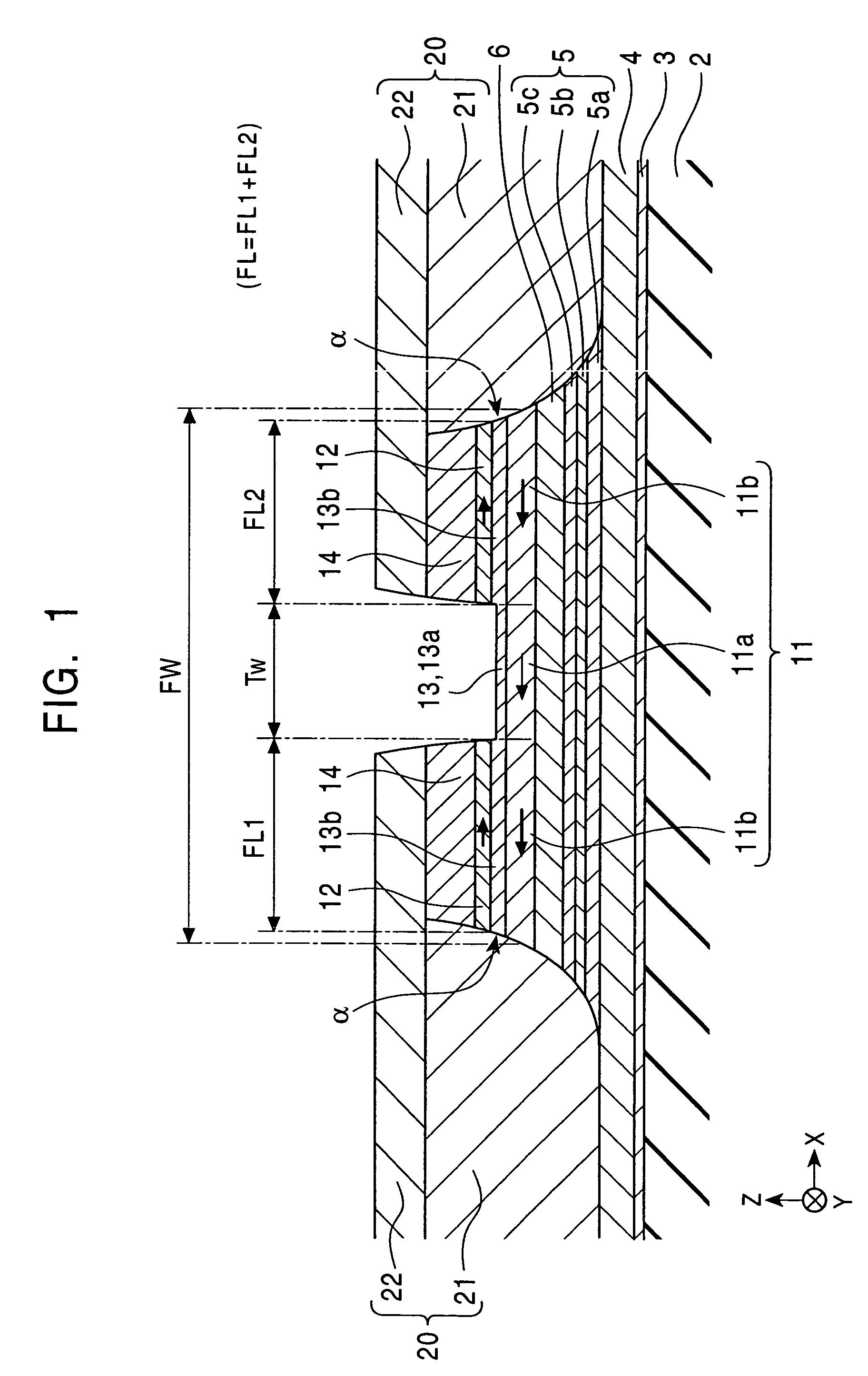
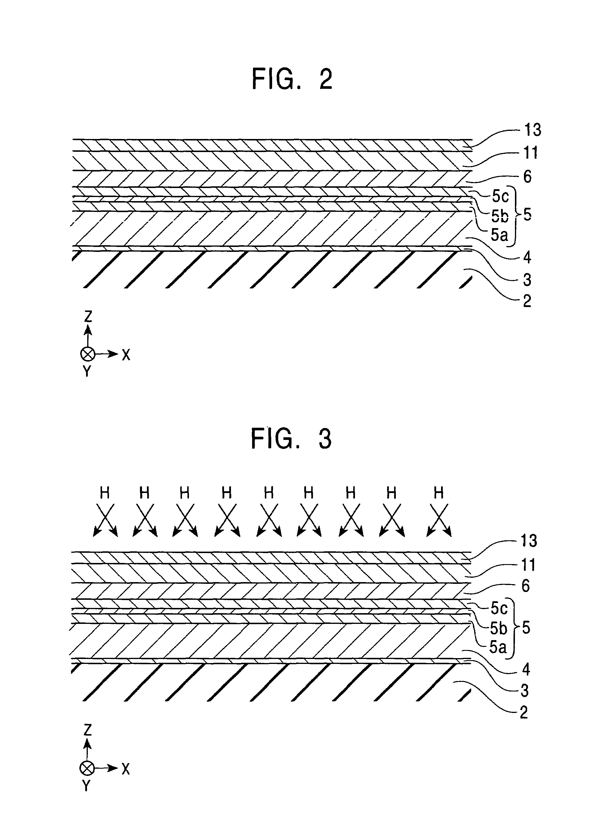
[0042]The present invention will be described below with reference to the drawings. In each of the drawing, the X direction coincides with the track width direction, the Y direction coincides with the direction of a leakage magnetic field from a recording medium, and Z direction coincides with the movement direction of the recording medium and the lamination direction of layers constituting a giant magnetoresistive element.

[0043]FIG. 1 is a schematic sectional view showing the structure of a giant magnetoresistive (GMR) element 1 according to a first embodiment of the present invention, as viewed from a surface facing the recording medium. The GMR element 1 is used for, for example, a thin film magnetic head of a hard disk device, for detecting a leakage magnetic field from the recording medium by utilizing a GMR effect.

[0044]The GMR element 1 is formed on a lower gap layer 2 comprising an insulating material such as alumina (Al2O3) or the like. The GMR element 1 comprises a seed la...


PUM

PropertyMeasurementUnit
RKKY coupling energyaaaaaaaaaa
giant magnetoresistiveaaaaaaaaaa
antiferromagneticaaaaaaaaaa

Abstract

A giant magnetoresistive (GMR) element includes a first antiferromagnetic layer, a pinned magnetic layer having a magnetization direction pinned by the first antiferromagnetic layer, a nonmagnetic material layer, a free magnetic layer having a magnetization direction with a central portion changing with an external magnetic field, a nonmagnetic layer, ferromagnetic layers formed on both sides of the nonmagnetic layer, and second antiferromagnetic layers for aligning the magnetization direction of the ferromagnetic layers perpendicular to that of the pinned magnetic layer. The magnetization directions of the free magnetic and ferromagnetic layers are antiparallel to each other. At least the free magnetic layer, the nonmagnetic layers and the ferromagnetic layers have continuous surfaces α at both end surfaces in the track width direction. First electrode layers are provided in contact with the continuous surfaces α, and second electrode layers are provided on the first electrode layers and the second antiferromagnetic layers.

Description

BACKGROUND OF THE INVENTION[0001]1. Field of the Invention[0002]The present invention relates to a giant magnetoresistive element used for a hard disk device, a magnetic sensor, and the like, and a method of manufacturing the same.[0003]2. Description of the Related Art[0004]In a giant magnetoresistive element (GMR) used for a hard disk device, a magnetic sensor, and the like, an improvement in output sensitivity and narrowing of a track have recently been advanced with increases in the recording density.[0005]In order to improve the output sensitivity, a magnetic moment (areal moment) per unit area of a free magnetic layer is conventionally decreased by thinning the free magnetic layer to facilitate magnetization rotation of the magnetic moment. However, with the thin free magnetic layer, Barkhausen noise, thermal fluctuation noise, and the like are increased to cause the problem that a SN ratio cannot be increased even by increasing the output sensitivity. Also, a hard bias system...

Claims


Application Information

Patent Timeline
Patent Type & Authority Patents(United States)
IPC IPC(8): G11B5/39G11B5/127G01R33/09H01F10/32H01L43/08H01L43/12
CPCB82Y10/00B82Y25/00G01R33/093H01F10/3268G11B5/3903G11B5/3932G11B5/3967G11B2005/3996
Inventor HASEGAWA, NAOYA
Owner TDK CORPARATION
Why Eureka
Try Eureka