Multi-user detection method

a detection method and multi-user technology, applied in the field of multi-user detection, can solve the problems of multi-path interference, large interference with detection, incomplete separation, etc., and achieve the effect of improving the elimination of multi-user interference, simple and precis

Inactive Publication Date: 2006-07-18
MITSUBISHI ELECTRIC CORP
View PDF1 Cites 23 Cited by
  • Summary
  • Abstract
  • Description
  • Claims
  • Application Information

AI Technical Summary

Benefits of technology

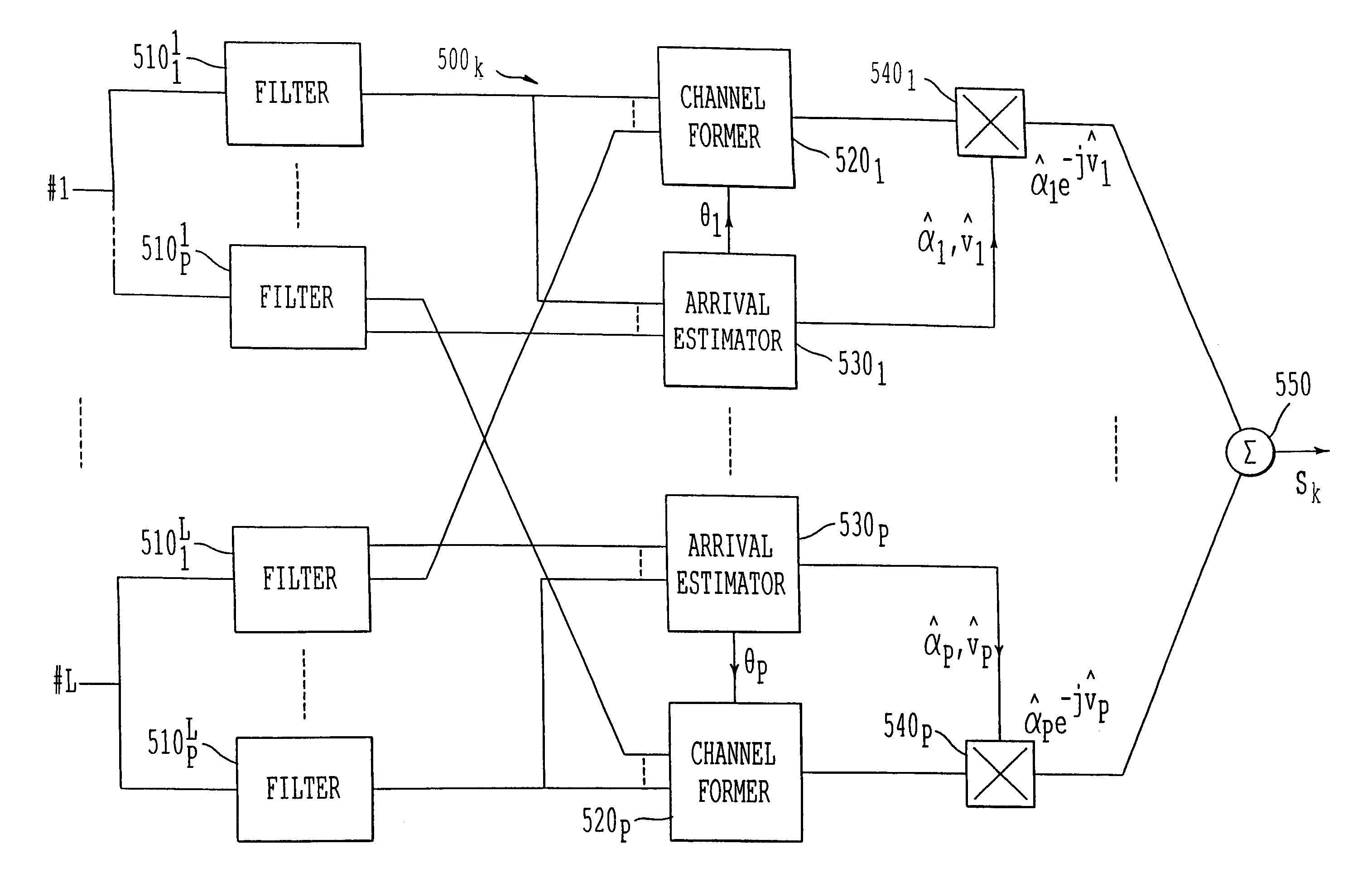
[0014]One aim of the present invention is to propose a detection method and device which improve the elimination of the multi-user interference in the presence of multi-path channels. A subsidiary aim of the present invention is the simple and precise determination of the attenuation coefficients and the phase rotations relating to the paths of the transmission channels of the different users.

Problems solved by technology

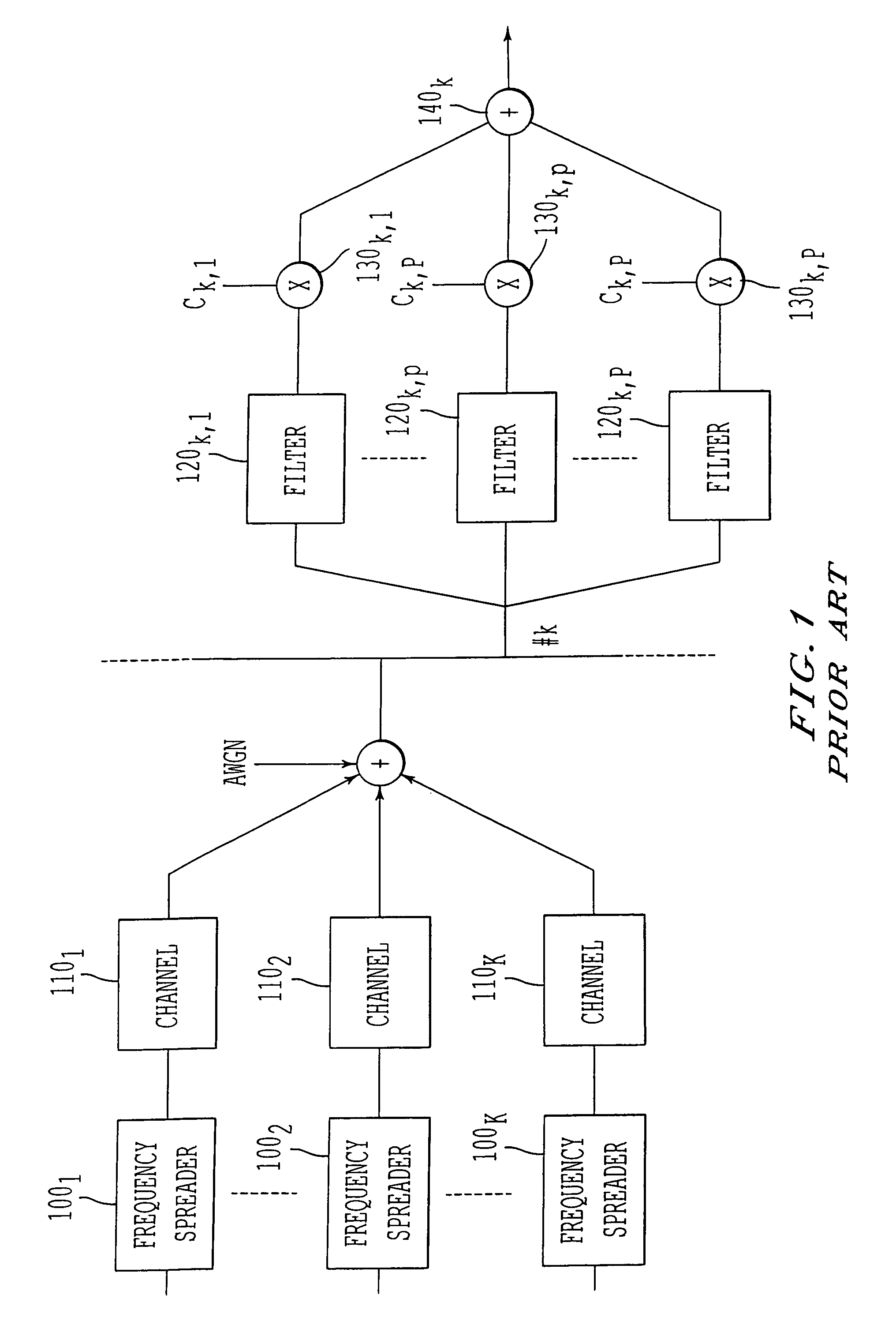
In practice, however, the separation is not complete and leaves a multipath interference which is also referred to as self noise. FIG. 1 depicts schematically a DS-CDMA system with K users.
This is particularly the case in a so-called near-far effect situation, where a high-power signal received from a user interferes with the reception of a low-power signal coming from another user.
Moreover, when the number of users is high, close to the spread factor, the sum of the interferences of the different users, low if taken in isolation, can have effects which interfere greatly with detection.
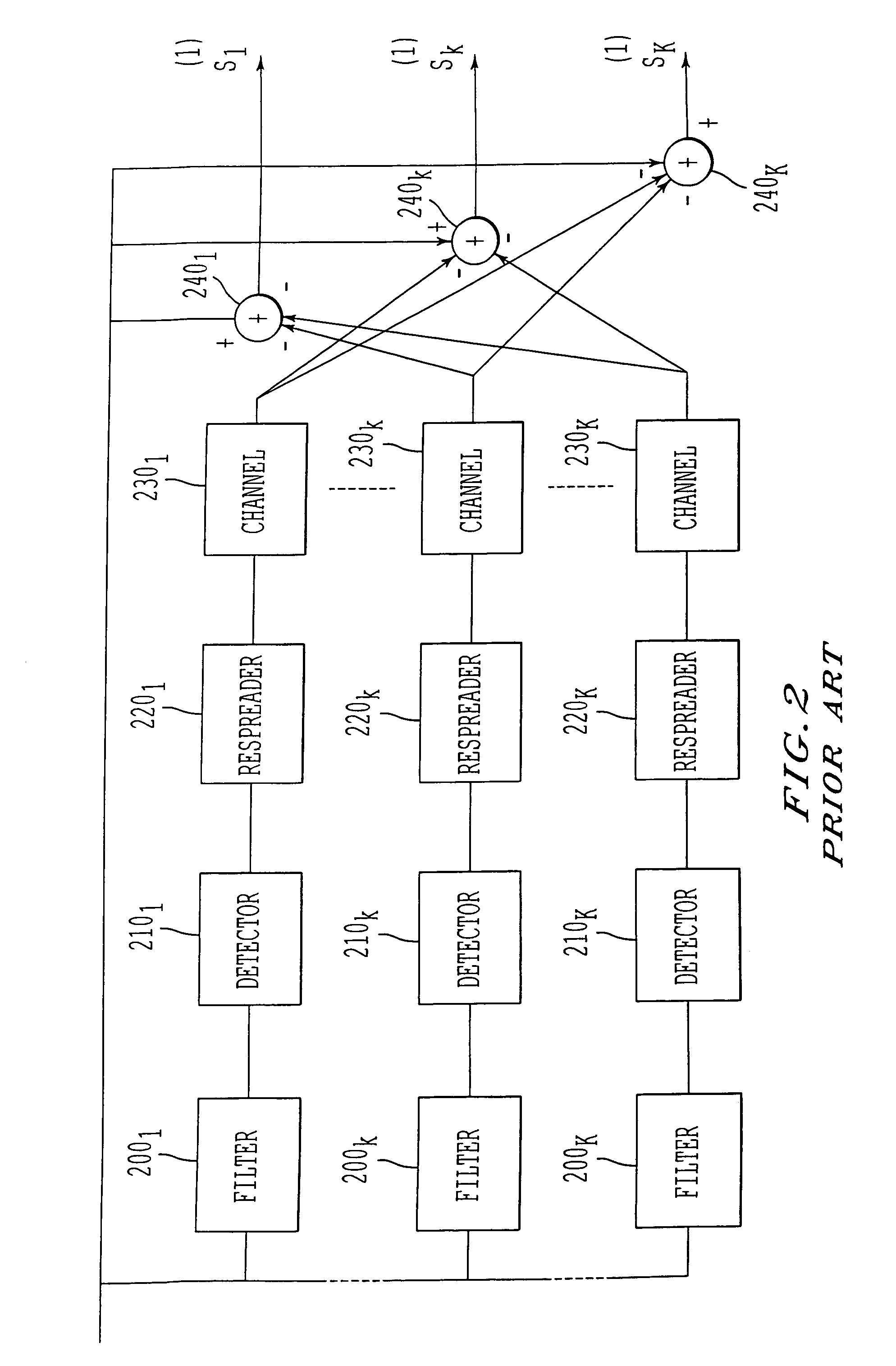
When the channels are multi-path, the situation is on the other hand much more complex since it is necessary at the same time to eliminate multi-path interference and multi-user interference.
However, this determination is often imprecise, which results in an imperfect or even erroneous elimination of the multi-user interference.

Method used


Image

  • Multi-user detection method
  • Multi-user detection method
  • Multi-user detection method

Examples


fourth embodiment

[0083]FIG. 9a depicts a multi-user detection device according to the invention.

[0084]This embodiment extends the parallel elimination mode in the sense that it now includes a “multi-equalisation” function which will be explained later. The reference numbers indicated are equivalents to those of FIG. 6 when they correspond to identical functions. The device depicted in FIG. 9a nevertheless differs from that in FIG. 6 in that it comprises a linear filter (905) upstream of the decision modules (910k). The purpose of this filtering is to take into account the outputs of the receivers of the rake type (900k) at different sampling times in the elimination of the interference. The filter (905) is a transverse linear time filter which fulfils a role equivalent to that of a conventional transverse linear equaliser when a single user is considered. Unlike the latter, however, the filter (905) is a matrix filter which operates on vectors of size K and therefore uses matrices of size K×K instea...

fifth embodiment

[0086]FIG. 10 depicts a multi-user detection device according to the invention.

[0087]This embodiment transposes the technique of equalisation by decision feedback (DF) to the multi-user context. The modules (1000), (1010), . . . (1080) are modules identical to the modules (900), (910), . . . , (980) of FIG. 9, each module operating, as stated, on a vector with K components. The module corresponding to 960 has been depicted here in two parts (1061) and (1062) in order to separate the modulation function (1061) from the spectral spreading function (1062). The device comprises a precursor transverse filter (1005) identical to the filter (905) and a postcursor filter (1007) filtering the reinterleaved and remodulated output of the module (1061). The output of the postcursor filter (1007) is subtracted (at 1006) from the output of the precursor module (1005) and the result is provided as an input to the decision module (1010). The assembly consisting of the transverse filter (1005) and f...


PUM


Abstract

A multi-user detection method eliminating interference between users transmitting modulated data of symbols on a transmission channel, each transmission channel including at least one propagation path arriving at an array of reception antennas in a direction of arrival. Each user (a) estimates the signal transmitted by the user from the antenna signals, effecting estimation of the direction of arrival and characteristics of propagation of each path of the transmission channel from the signals; (b) estimates the data transmitted by the user from the estimation of the signal transmitted; (c) estimates the contribution of the user to the signals received by the different antennas from the estimated data and the estimated direction of arrival and propagation characteristics; and (d) subtracts from the antenna signals the contribution estimated at (c) to obtain cleaned antenna signals, supplied by at least a first sequence, used as antenna signals by at least a second sequence.

Description

BACKGROUND OF THE INVENTION[0001]1. Field of the Invention[0002]The present invention concerns in general terms a Multi-User Detection (MUD) method. More precisely, the present invention relates to an iterative method of eliminating interference between users (Multiple Access Interference or MAI). The present invention applies more particularly to mobile telephony in DS-CDMA (Direct Sequence-Code Division Multiple Access) mode, that is to say to mobile telephony using a code distribution access mode with direct sequence spectral spreading.[0003]2. Discussion of the Background[0004]In a DS-CDMA mobile telephony system, the separation of the different users is effected by multiplying each user symbol by a spreading sequence peculiar to it, also referred to for this reason as the user signature, the different signatures ideally being chosen so as to be orthogonal. The spreading sequence frequency (chip rate) being greater than the frequency of the symbols, the signal transmitted by eac...

Claims


Application Information

Patent Timeline
Patent Type & Authority Patents(United States)
IPC IPC(8): H03D1/04H03D1/06H03K5/01H03K6/04H04B1/10H04B1/707H04B7/08
CPCH04B1/7103H04B7/086H04B1/7107H04B1/7117
Inventor BRUNEL, LOIC
Owner MITSUBISHI ELECTRIC CORP
Why Eureka
Try Eureka