Method for controlling engine air/fuel ratio

a technology of engine air and fuel ratio, applied in the direction of electric control, machines/engines, mechanical equipment, etc., can solve the problem of reducing the engine air/fuel ratio

Inactive Publication Date: 2006-07-25
DETROIT DIESEL CORP
View PDF21 Cites 28 Cited by
  • Summary
  • Abstract
  • Description
  • Claims
  • Application Information

AI Technical Summary

Benefits of technology

[0008]The invention comprehends bringing the air / fuel ratio down to an intermediate level through engine air flow management during the LNT regeneration process. More specifically, in a supercharged or turbocharged engine including a compressor at the intake, recirculating some air from the compressor discharge back to the compressor inlet reduces the engine air / fuel ratio. This approach alleviates much of the requirements on the fuel injection side that are typically associated with LNT regeneration. Further reduction of the air / fuel ratio can be achieved via fuel injection into the combustion chamber and / or fuel injection in the exhaust stream.
[0010]Similarly, this approach can be used to increase exhaust temperature for more rapid catalyst light off or move the exhaust temperature to a range where catalyst efficiency is higher.

Problems solved by technology

More specifically, in a supercharged or turbocharged engine including a compressor at the intake, recirculating some air from the compressor discharge back to the compressor inlet reduces the engine air / fuel ratio.

Method used


Image

  • Method for controlling engine air/fuel ratio
  • Method for controlling engine air/fuel ratio
  • Method for controlling engine air/fuel ratio

Examples


Embodiment Construction

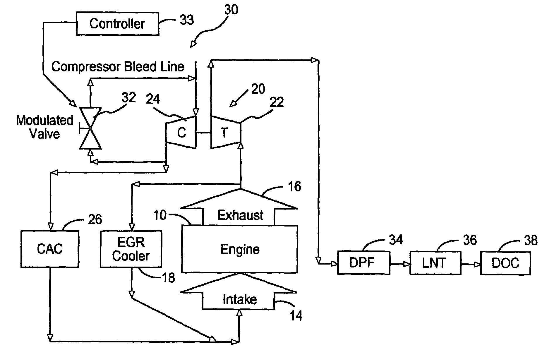
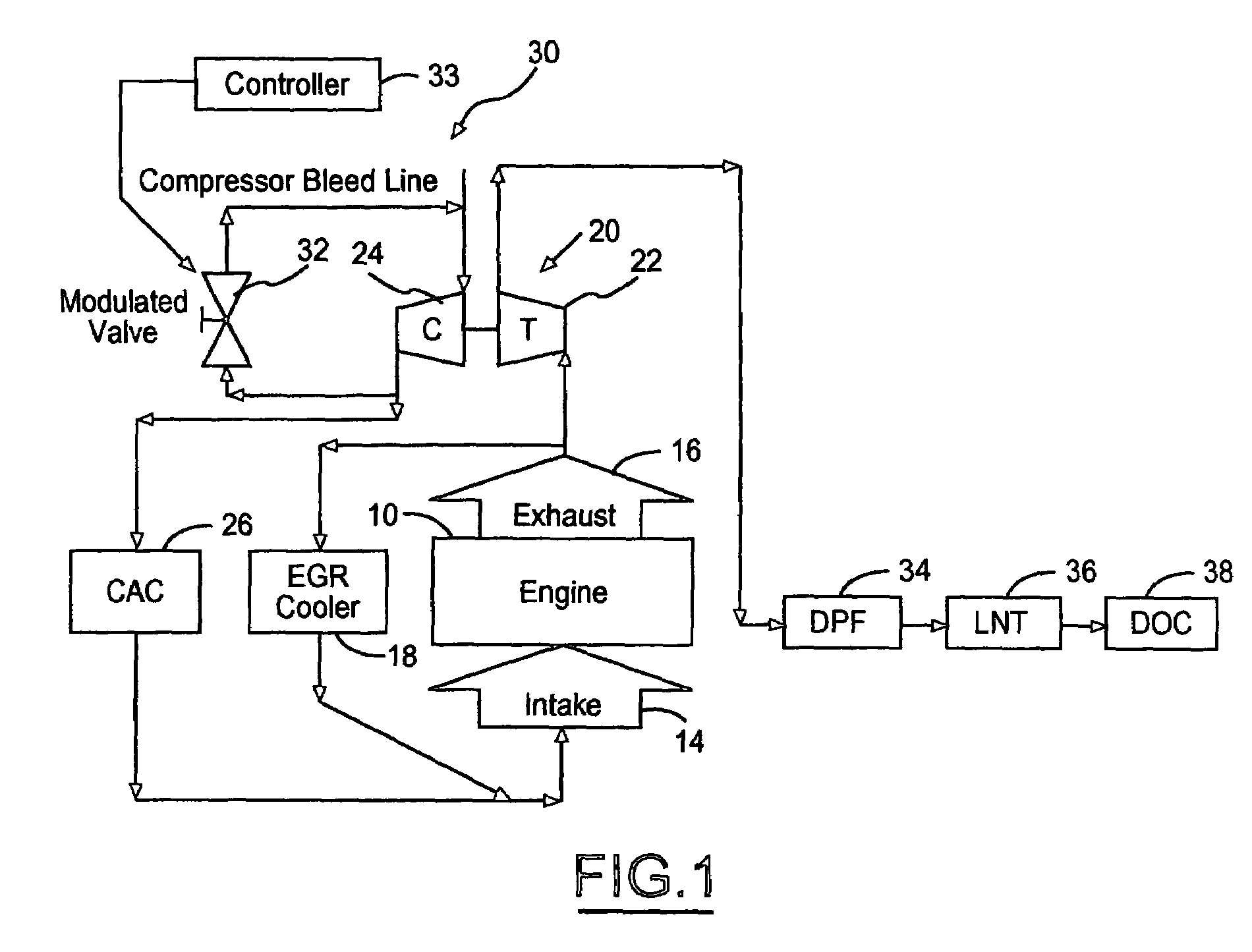
[0014]With reference to FIG. 1, an engine 10 includes a plurality of cylinders fed by fuel injectors. The engine intake is indicated at 14 while the engine exhaust is indicated at 16. In the illustrated preferred embodiment, the engine is equipped with an exhaust gas recirculation (EGR) system. The EGR system recirculates a portion of the exhaust gases back to the engine intake 14, as needed, to avoid excessively high combustion temperatures which cause NOx creation. EGR cooler 18 cools the recirculated exhaust gas prior to introduction at engine intake 14.

[0015]As shown, the engine is equipped with a turbocharger system 20. System 20 includes turbine 22 driven by exhaust gases. Turbine 22 drives compressor 24. Charge air cooler (CAC) 26 cools the charge air from compressor 24 prior to introduction at engine intake 14.

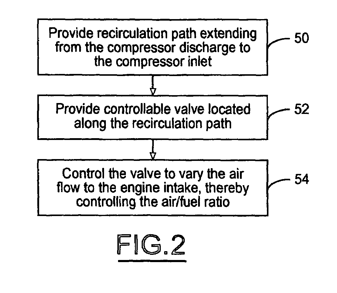
[0016]According to the invention, engine air flow management is utilized to reduce the engine air / fuel ratio. More specifically, a recirculation path 30 from the compr...


PUM


Abstract

A system for controlling engine air / fuel ratio includes an engine, a compressor having an inlet receiving air. The compressor discharges air to the engine intake. A recirculation path is provided from the compressor discharge to the compressor inlet. A controllable valve is located along the recirculation path. A controller is programmed to control the valve to vary the air flow to the engine intake, thereby controlling the air / fuel ratio. Various applications for the compressor recirculation arrangement are possible.

Description

STATEMENT REGARDING FEDERALLY SPONSORED RESEARCH OR DEVELOPMENT[0001]This invention was made with Government support under Contract No. DE-FC02-99EE50575. The Government may have certain rights to this invention.BACKGROUND OF THE INVENTION[0002]1. Field of the Invention[0003]The invention relates to a method for controlling engine air / fuel ratio.[0004]2. Background Art[0005]After-treatment devices such as Lean NOx Traps (LNT) are being devised to adsorb NOx emissions from diesel engines in an effort to meet future emission standards. LNTs can be very effective in trapping NOx but need to be periodically cleaned through a regeneration process. A rich environment (close to an air / fuel ratio of 14) is required to regenerate the trap. While fuel injection in the combustion chamber and / or fuel injection in the exhaust stream can effectively reduce the exhaust air / fuel ratio, they both present some limitations in terms of how much fuel can be injected. Too much fuel injected in the combus...

Claims


Application Information

Patent Timeline
Patent Type & Authority Patents(United States)
IPC IPC(8): F02B33/44F01N3/00F01N3/10F01N5/04F02B33/00
CPCF02B37/16F02D23/02F02D41/0007F02D41/0245F02D41/0275F02M25/0707F01N3/023Y02T10/26F01N2430/06F02B29/0406F02D41/0065F02D41/0235F02D41/029F02M25/0727Y02T10/144F01N3/206F02M26/05F02M26/23Y02T10/12
Inventor BOLTON, BRIAN KENNETHSISKEN, KEVIN DEANGROSMOUGIN, ANNE-LISE
Owner DETROIT DIESEL CORP
Why Eureka
Try Eureka