Cooled turbine spar shell blade construction

a turbine blade and spar shell technology, applied in blade accessories, machines/engines, mechanical equipment, etc., can solve the problems of reduced engine efficiency, reduced structural integrity of turbine components, and reduced efficiency of turbine cooling process, so as to achieve the effect of convenient fabrication

Inactive Publication Date: 2006-07-25
FLORIDA TURBINE TECH
View PDF8 Cites 87 Cited by
  • Summary
  • Abstract
  • Description
  • Claims
  • Application Information

AI Technical Summary

Benefits of technology

[0017]A feature of this invention is an improved turbine blade that is characterized as being easy to fabricate, provide efficacious cooling with lesser amounts of cooling air than heretofore known designs, provides a shell or shells that can be replaced and hence affords the user the option of repair or replace. The materials selected can be conventional or more esoteric depending on the specification of the engine.

Problems solved by technology

The problem that prevents the turbine from being operated at higher temperatures is the limitation of the structural integrity of the turbine component parts that are jeopardized in its high temperature, hostile environment.
The problem associated with internal cooling is twofold.
One, the cooling air that is utilized for the cooling comes from the compressor that has already expended energy to pressurize this air and the spent air in the turbine cooling process in essence is a deficit in engine efficiency.
The second problem is that the cooling is through cooling passages and holes that are in the turbine blade which, obviously, adversely affects the blade's structural prowess.
While there are materials that are available and can operate at a higher temperature that is heretofore been used, the problem is how to harness these materials so that they can be used efficaciously in the turbine environment.
Needless to say these parameters have limitations.
Obviously, the rotational speed of the turbine has a significant impact on the loadings.

Method used


Image

  • Cooled turbine spar shell blade construction
  • Cooled turbine spar shell blade construction
  • Cooled turbine spar shell blade construction

Examples


Embodiment Construction

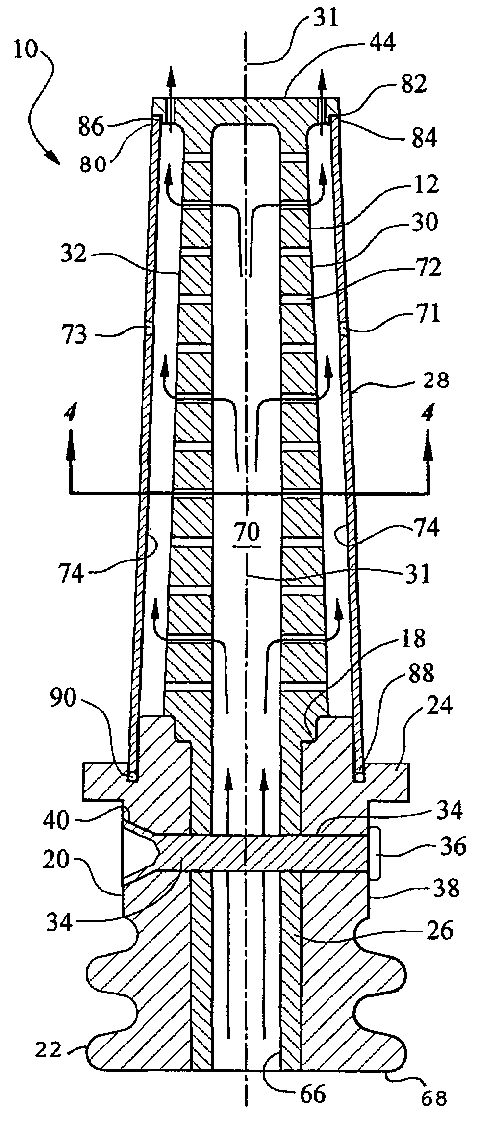
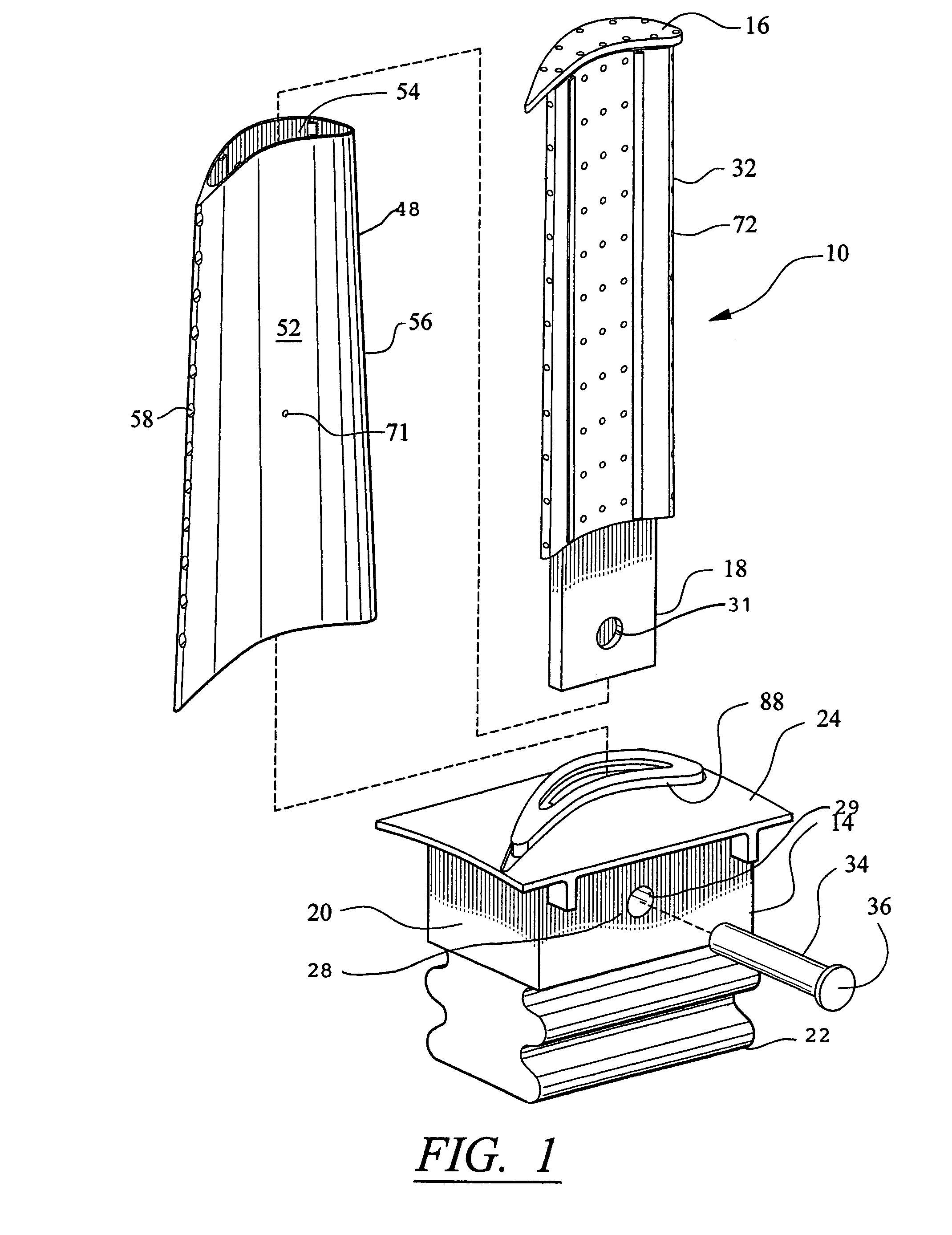
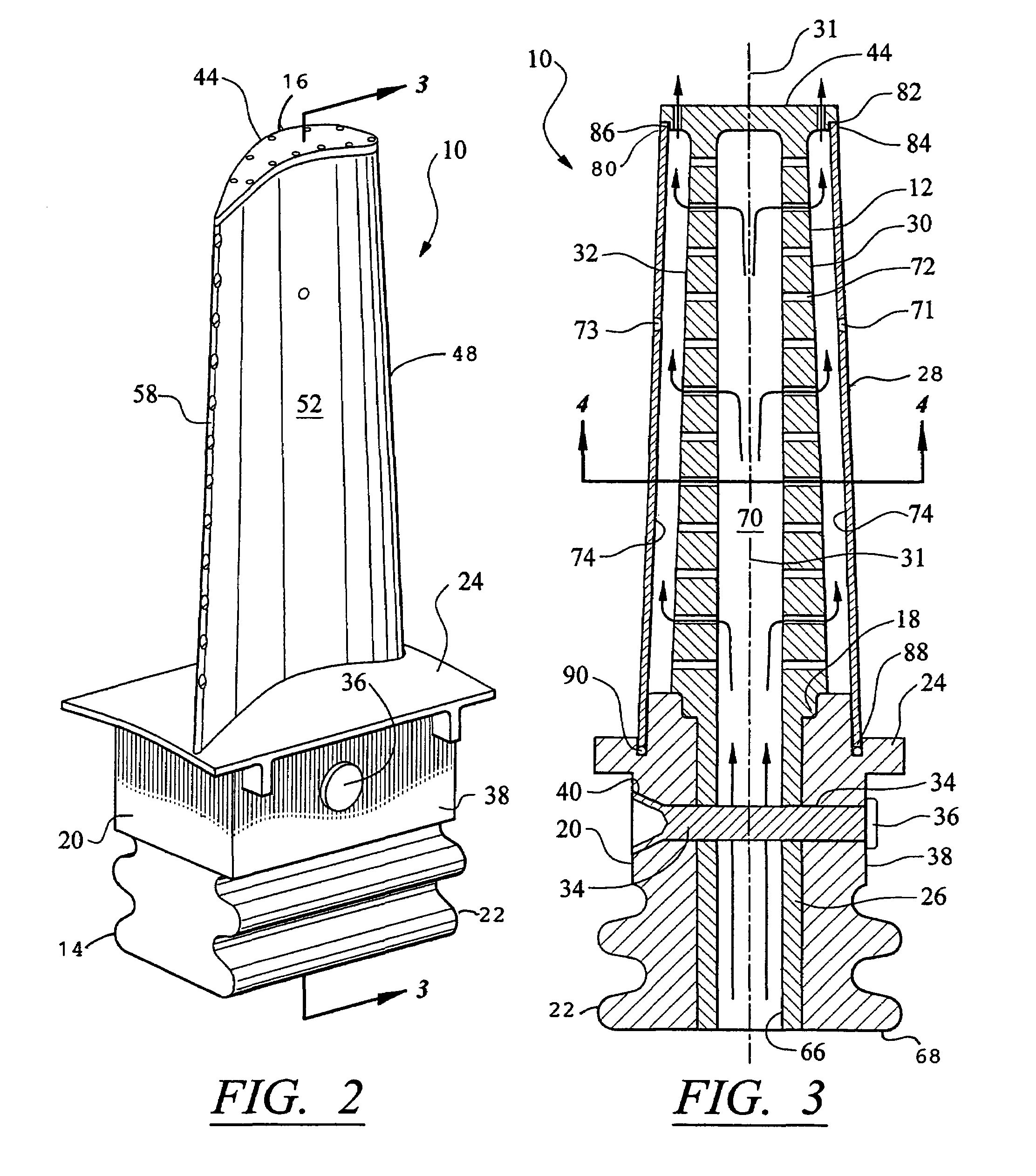
[0026]While this invention is described in its preferred embodiment in two different, but similar configurations so as to take advantage of engine's that are designed at higher speeds than are heretofore encountered, this invention has the potential of utilizing conventional materials and improving the turbine rotor by enhancing its efficiency by providing the desired cooling with a lesser amount of compressor air, and affords the designer to utilize a more exotic material that has higher resistance temperatures while also maintaining the improved cooling aspects. Hence, it will be understood to one skilled in this technology, the material selected for the particular engine design is a option left open to the designer while still employing the concepts of this invention. For the sake of simplicity and convenience only a single blade in each of the embodiments is described although one skilled in this art that the turbine rotor consists of a plurality of circumferentially spaced blad...


PUM

PropertyMeasurementUnit
pressureaaaaaaaaaa
temperatureaaaaaaaaaa
pressure ratioaaaaaaaaaa

Abstract

A blade for a rotor of a gas turbine engine is constructed with a spar and shell configuration. The spar is constructed in an integral unit or multi-portions and includes a first wall adjacent to the pressure side and a second wall adjacent to the suction side, a tip portion extending in the spanwise direction and extending beyond the first wall and the second wall and a root portion extending longitudinally, an attachment portion having a central opening for receiving the root portion and a platform portion. The root portion fits into the central opening and is secured therein by a pin extending transversely through the attachment and the root portion. The shell fits over the spar and is supported thereto by a plurality of complementary hooks extending from the spar and shell. The ends of the shell fit into grooves formed on the tip portion and the platform.

Description

[0001]This application claims benefit of a prior filed co-pending U.S. provisional application Ser. No. 60 / 454,120, filed on Mar. 12, 2003, entitled “COOLED TURBINE BLADE by Jack Wilson and Wesley Brown.FEDERALLY SPONSORED RESEARCH[0002]NoneTECHNICAL FIELD[0003]This invention relates to internally cooled turbine blades for gas turbine engines and more particularly to the construction of the internally cooled turbine comprising a spar and shell construction.BACKGROUND OF THE INVENTION[0004]As one skilled in the gas turbine technology recognizes, the efficiency of the engine is enhanced by operating the turbine at a higher temperature and by increasing the turbine's pressure ratio. Another feature that contributes to the efficacy of the engine is the ability to cool the turbine with a lesser amount of cooling air. The problem that prevents the turbine from being operated at higher temperatures is the limitation of the structural integrity of the turbine component parts that are jeopar...

Claims


Application Information

Patent Timeline
Patent Type & Authority Patents(United States)
IPC IPC(8): F01D5/18F01D5/00
CPCF01D5/147F01D5/189Y10T29/49341Y10T29/49327Y10T29/49339F01D5/20
Inventor WILSON, JACK W.BROWN, WESLEY
Owner FLORIDA TURBINE TECH
Why Eureka
Try Eureka