
Method of manufacturing a polymethylmethacrylate core shell nanocomposite optical plastic article

a technology of polymethylmethacrylate and core shell, applied in the field of plastic optical articles and films, can solve the problems of high cost, laborious grinding and polishing, and high temperature at which glass must be formed, and achieves the effects of high production efficiency, high production efficiency, and high production efficiency

Inactive Publication Date: 2006-07-25
APPLE INC
View PDF22 Cites 16 Cited by
  • Summary
  • Abstract
  • Description
  • Claims
  • Application Information

AI Technical Summary

Benefits of technology

The solution achieves reduced temperature sensitivity and low haze in nanocomposite materials, maintaining transparency and stability similar to the plastic host, enabling the production of optical articles with improved thermal stability and processing characteristics.

Problems solved by technology

The difference in cost is due largely to the difference in manufacturing processes that are required for the two materials and the relative temperatures that the materials must be formed at.
Plastic lenses are typically produced at 230° C. using injection molding at cycle times that are 10 times faster than glass lenses that are largely produced by grinding and polishing or compression molding at 625° C. Grinding and polishing are labor intensive while the high temperatures that glass must be formed at requires expensive mold materials and extensive maintenance costs.
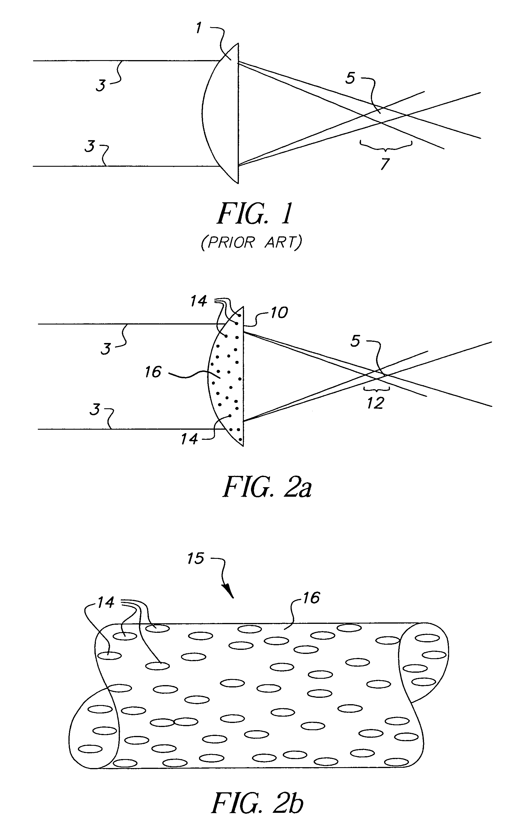
In optical plastics however, the electronic polarizability is very small compared to the density change so that all unfilled plastic materials have negative dn / dT values.
In experiments and computer modeling done at Eastman Kodak, it has been noted that the addition of even very small nanoparticles (10–40 nm) into plastic host materials can lead to low level light scattering or haze in the nanocomposite material which limits light transmission to less than 90%.
While there have been several attempts to modify properties of plastics using nanoparticles, none of these attempts have proven successful in producing optical plastic articles with improved temperature stable optical properties while retaining important processing characteristics and low levels of haze.
However, James et al. do not contemplate the impact of the particles or the coating material on the overall thermal stability of the refractive index of the nanocomposite material.

Method used


Image

  • Method of manufacturing a polymethylmethacrylate core shell nanocomposite optical plastic article
  • Method of manufacturing a polymethylmethacrylate core shell nanocomposite optical plastic article
  • Method of manufacturing a polymethylmethacrylate core shell nanocomposite optical plastic article

Examples


example 1

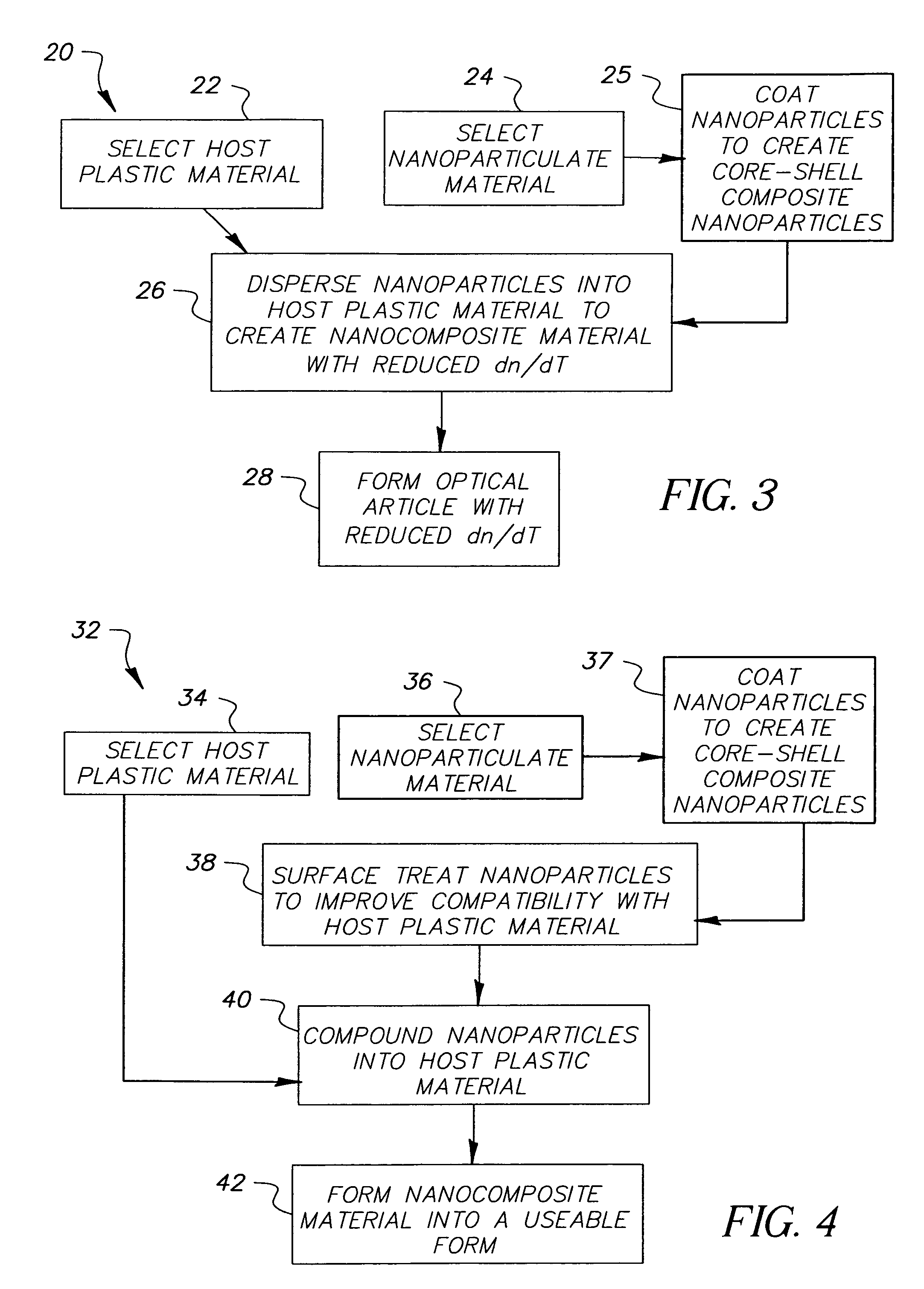
[0056]An example of the aforementioned method for reducing dn / dT of an optical plastic while retaining excellent transparency follows:

[0057]Three (3) samples were prepared using a polymethylmethacrylate polymeric base material (n=1.49) and nanoparticle fillers of approximately 15 nm size. The nanoparticles were all solvent dispersed at approximately 4% loading. The first sample was made with silica nanoparticles (n=1.45) and it was very clear. This result is due to the fact that the silica nanoparticles have nearly the same index of refraction as the polymethylmethacrylate plastic host material (1.49 vs 1.45) and light scattering does not occur to an appreciable extent. The second sample was made with magnesium oxide nanoparticles (n=1.72) and it was quite hazy. The third sample was made with zinc sulfide nanoparticles (n=2.35) and it was nearly opaque.

[0058]Observations of relative levels of haze produced in the 3 samples were supported by calculated values from a light scattering ...

example 2

[0060]A further example shows the importance of the coating thickness on the level of haze produced by composite nanoparticles. Again, the light scattering model was used to evaluate the haze levels produced by composite nanoparticles with various shell thicknesses. Three (3) coating thicknesses were evaluated with 4% zinc sulfide (n=2.35) nanoparticles in polymethylmethacrylate (n=1.49). The zinc sulfide nanoparticles were 20 nm and coated with silica (n=1.45) with the coating thicknesses being 5 nm, 8 nm and 17 nm where the 17 nm thick coating is the optimum thickness as calculated by Equation 1. The results showed haze levels of 44%, 29%, and 2% respectively which shows that coating thickness is important to produce the lowest haze level.

example 3

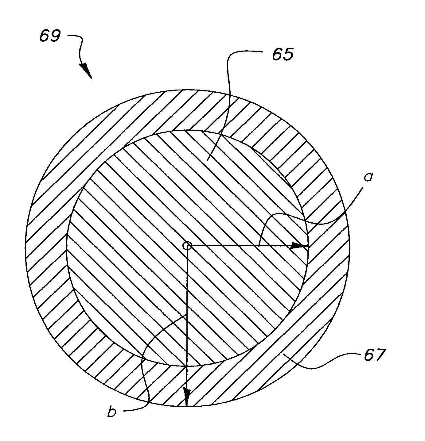
[0061]Another example shows the impact of different types of coatings on optimum coating thickness. The light scattering model was again used to evaluate material combinations and the effect on haze. In this case, 10 nm zinc sulfide (n=2.35) nanoparticles coated with 3 nm of magnesium fluoride (n=1.38) and loaded to 4% in a polycarbonat a haze level of only 1%. In this case, the refractive index of the coating is quite different from the plastic host refractive index, 1.38 vs 1.59. Consequently the coating thickness does not need to be as thick as the case examined in Example 2 where the coating had to be 5 times as thick (17 nm) because the refractive index of the coating was close to that of the plastic host, 1.45 vs 1.49.

[0062]The invention has been described with reference to a preferred embodiment. However, it will be appreciated that variations and modifications can be effected by a person of ordinary skill in the art without departing from the scope of the invention.


PUM

PropertyMeasurementUnit
particle sizeaaaaaaaaaa

Abstract

A nanocomposite optical plastic article has a plastic host material with a temperature sensitive optical vector (x) and a core shell nanoparticulate material dispersed into the plastic host material. The core shell nanoparticulate material is characterized by a core defined by a nanoparticulate material which has a temperature sensitive optical vector (x1) and a shell defined by a coating material layer coated onto the core. It is important to the invention that temperature sensitive vector (x1) is directionally opposed to the temperature sensitive optical vector (x) and nshell<nplastic host<ncore.

Description

FIELD OF THE INVENTION[0001]The invention relates generally to the field of plastic optical articles and films. More particularly, the invention concerns plastic optical materials and articles containing core shell composite nanoparticles, such as plastic lenses, optical films, and optical couplers, that must maintain stable performance characteristics over a broad temperature range.BACKGROUND OF THE INVENTION[0002]Plastic lenses and glass lenses often perform the same function in optical systems, such as in cameras, microscopes, telescopes, and opthalmic wear. The two main attributes that separate plastic lenses from glass lenses are cost and optical stability. Plastic lenses typically cost 1 / 100th the price of a similar glass lens while the stability of the refractive index of a glass lens with respect to temperature and humidity is typically 100 times better than that of a plastic lens.[0003]The difference in cost is due largely to the difference in manufacturing processes that a...

Claims


Application Information

Patent Timeline
Patent Type & Authority Patents(United States)
IPC IPC(8): B32B5/16C09C1/02C09C1/04G02B1/04
CPCB82Y30/00C09C1/028C09C1/04G02B1/04C08L33/12C01P2004/64Y10T428/2998Y10T428/254
Inventor JAMES, ROBERT O.ROWLEY, LAWRENCE A.HURLEY, DANIEL F.BORDER, JOHN
Owner APPLE INC
Learn More