Method for thermally processing photosensitive printing sleeves

a printing sleeves and thermal processing technology, applied in the field of thermal processing of photosensitive printing sleeves, can solve the problems of increasing the difficulty of making requiring a large amount of force (approximately 100 pounds/linear inch), and increasing the difficulty of printing elements of different sizes. to achieve the effect of reducing the variation of the floor layer

Active Publication Date: 2006-07-25
MACDERMID PRINTING SOLUTIONS
View PDF29 Cites 23 Cited by
  • Summary
  • Abstract
  • Description
  • Claims
  • Application Information

AI Technical Summary

Benefits of technology

[0020]It is an object of the present invention to minimize relief variation in the floor layer of photosensitive printing sleeves.
[0021]It is another object of the present invention to improve image fidelity on the printing surface.
[0022]To that end, the present invention is directed to an improved method of manufacturing photosensitive printing elements that minimizes relief variation and improves image fidelity and to an improved cylindrical photosensitive printing element made by the process of the invention that can be thermally developed.
[0028]iv) a masking layer on top of the at least second layer of photocurable material that allows for the selective polymerization of the at least second layer of photocurable material;

Problems solved by technology

This increases the difficulty in making printing elements of different sizes.
In addition, additional problems may arise when attempting to make the blotting machine larger to accommodate larger printing elements.
Another problem with the current blotting methods is that a tremendous amount of force (approximately 100 pounds / linear inch) must be applied by the heated roll to force the blotting material into the image on the printing element.
This large force can cause the heated roll to bend, resulting in an uneven floor.
In addition, the biggest downfall to the commercialization of thermally produced plates is relief variation.
Due to the fact that not all of the uncured resin may get processed, the amount of resin that actually gets removed can be affected by various conditions in the process.
Next, the actual set up conditions in the thermal processor, such as the number of cycles and the processing temperature, can affect uncured resin removal in a non-uniform manner.
Thus, it is highly likely that the final process will result in residual un-cured resin remaining on the plate that will then become cured during the resultant post-exposure steps.
A further complication of thermally processing plates is that the traditional process of producing seamless photopolymer sleeves can inherently produce floor variations.
However, for printing sleeves, the light exposure techniques that exist today are limited by the ability to expose the sleeve through the back side of the sleeve carrier, which ultimately results in an inherent floor variation.
This inherent variation can be further complicated by the thermal process itself, which defines the need for an improved method of eliminating this pitfall in the sleeve manufacturing process.
This requires additional time to transfer the printing element from the exposure device to the development device and can affect the quality of the finished plate as a result of handling the printing element.

Method used


Image

  • Method for thermally processing photosensitive printing sleeves
  • Method for thermally processing photosensitive printing sleeves
  • Method for thermally processing photosensitive printing sleeves

Examples


Embodiment Construction

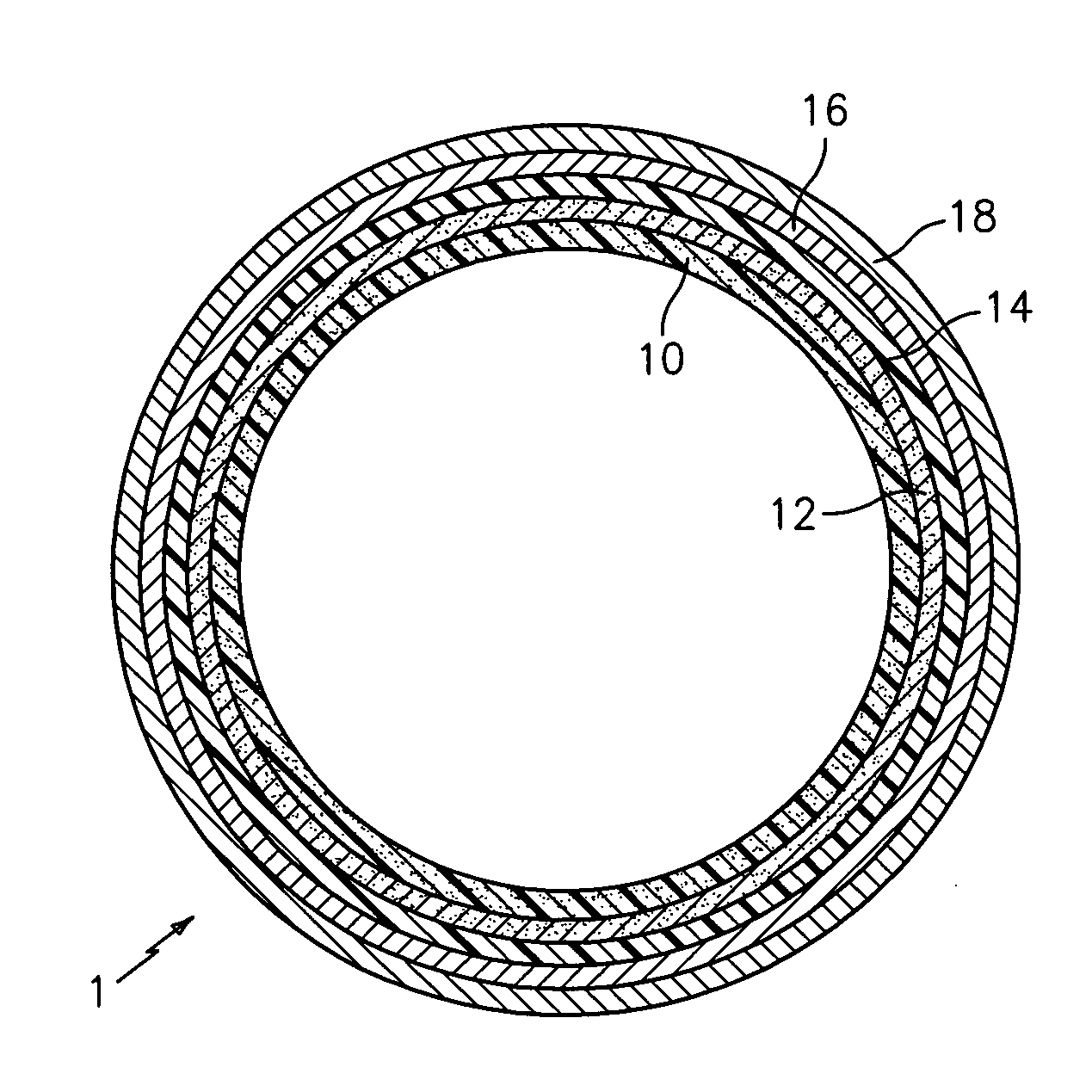
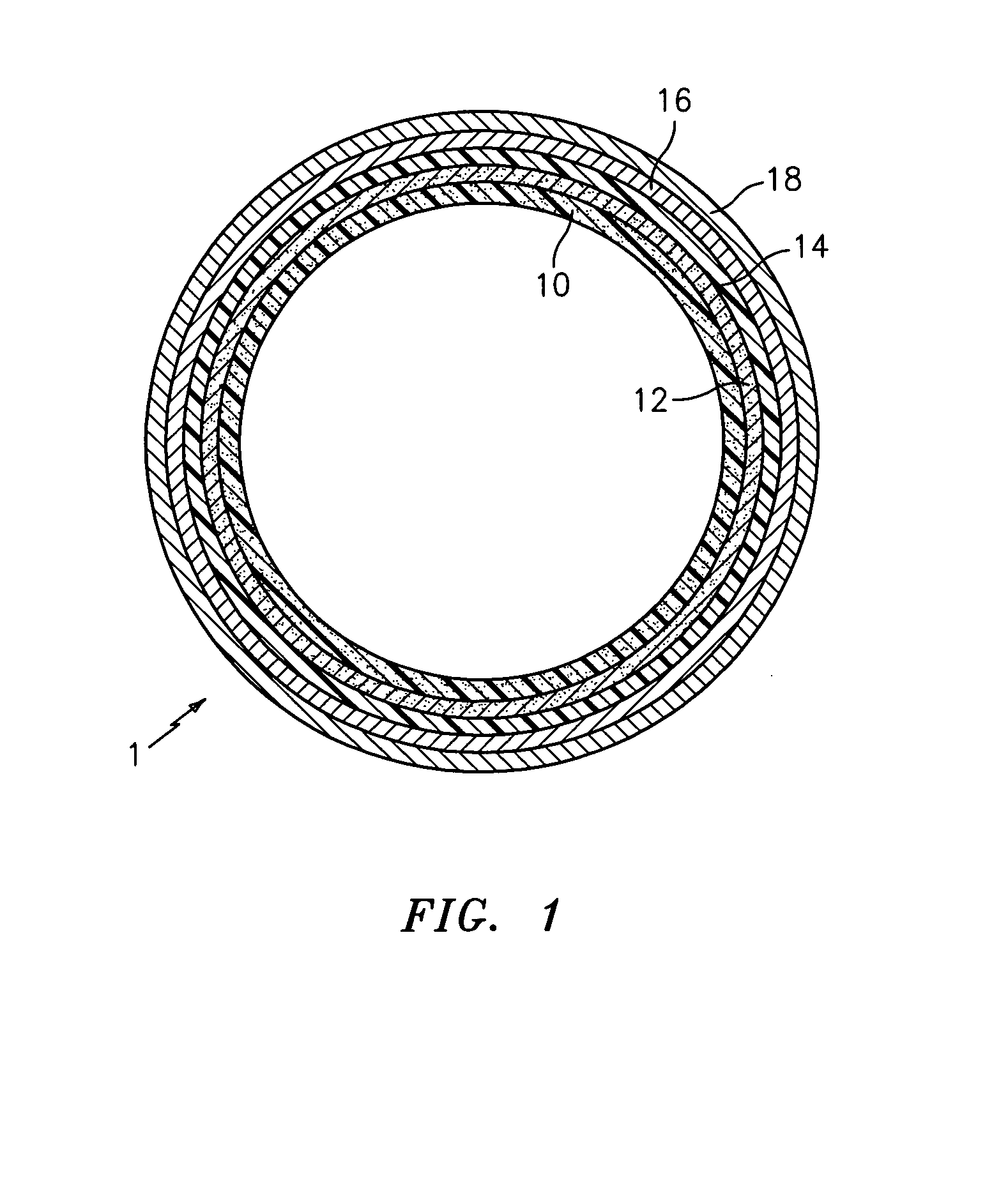
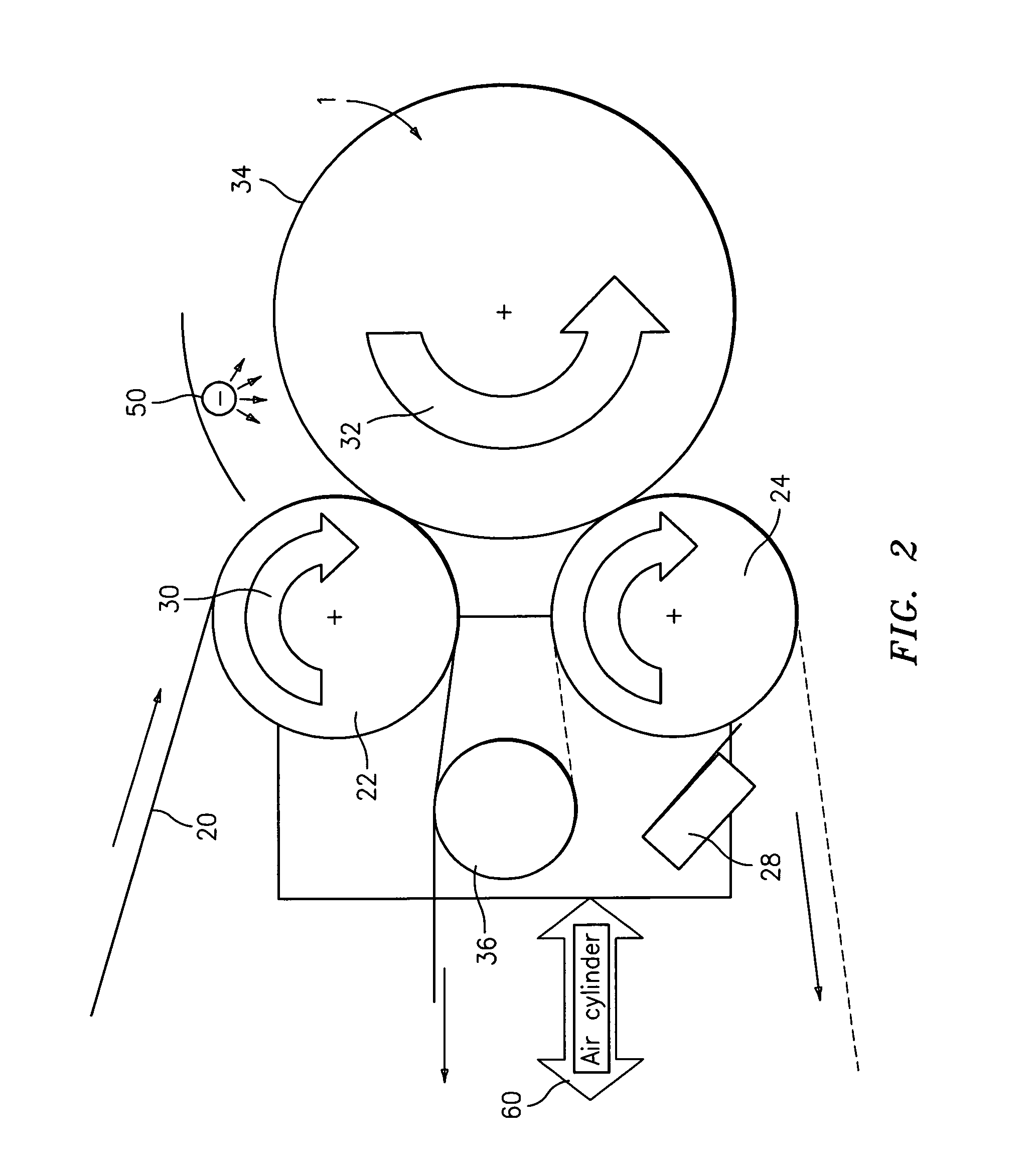
[0040]The present invention is directed to an improved method of thermally processing photosensitive printing sleeves that minimizes relief variation and improves image fidelity. The method of the invention pre-cures the floor layer of the photosensitive printing sleeve prior to removing non-crosslinked polymer from an imaged surface of the photosensitive printing element with at least one roll.

[0041]By pre-curing the first layer using traditional flood exposure techniques, the floor layer on the resultant printing element is more uniform from side to side. As a result, the image fidelity of the printing element is more pure, with fewer inconsistencies in the image areas across the sleeve. Furthermore, by pre-curing the first layer, the resultant floor layer is generally more tack free, reducing the tendency to build up ink, lint, and debris during the printing and storage process. The pre-cured floor also provides a distinct aesthetic advantage in the finished printing element, pro...


PUM

PropertyMeasurementUnit
temperatureaaaaaaaaaa
thicknessaaaaaaaaaa

Abstract

An improved method of manufacturing a photosensitive printing element that minimizes relief variation and improves image fidelity. The method involves a step of pre-curing the first (floor layer) of photocurable material prior to depositing an additional layer or layers of photocurable material that may be imaged and developed to produce a desired relief image on the surface of the photosensitive printing element. The photosensitive printing element is then thermally developed by contacting the photosensitive printing element with at least one roll that is capable of moving over at least a portion of the imaged surface of the flexographic printing element to remove the softened or melted non-crosslinked photopolymer. Non-crosslinked photopolymer on the imaged and exposed surface of the flexographic printing element can be softened or melted by positioning a heater adjacent to the imaged surface of the flexographic printing element and / or heating the at least one roll that contactable with the imaged surface of the flexographic printing element.

Description

FIELD OF THE INVENTION[0001]The present invention is directed to an improved method of thermally processing photosensitive printing sleeves that minimizes relief variation and improves image fidelity.BACKGROUND OF THE INVENTION[0002]Flexography is a method of printing that is commonly used for high-volume runs. Flexography is employed for printing on a variety of substrates such as paper, paperboard stock, corrugated board, films, foils and laminates. Newspapers and grocery bags are prominent examples. Coarse surfaces and stretch films can be economically printed only by means of flexography. Flexographic printing plates are relief plates with image elements raised above open areas. Such plates offer a number of advantages to the printer, based chiefly on their durability and the ease with which they can be made.[0003]Although photopolymer printing elements are typically used in “flat” sheet form, there are particular applications and advantages to using the printing element in a co...

Claims


Application Information

Patent Timeline
Patent Type & Authority Patents(United States)
IPC IPC(8): G03F7/09G03F7/26
CPCG03F1/00G03F1/68G03F7/11G03F7/343G03F7/36G03F7/34G03F1/003Y10S430/145Y10S430/146
Inventor VEST, RYAN
Owner MACDERMID PRINTING SOLUTIONS
Why Eureka
Try Eureka