Low voltage operation DRAM control circuits

a control circuit and low voltage technology, applied in the field of semiconductor memory, can solve the problems of exponential increase of sub-threshold leakage current flowing through the transistor, reduce the voltage, and reduce the performance (speed) of the transistor, so as to reduce the leakage current, reduce the charge flow, and increase the sense speed

Inactive Publication Date: 2006-07-25
ZMOS TECH
View PDF3 Cites 13 Cited by
  • Summary
  • Abstract
  • Description
  • Claims
  • Application Information

AI Technical Summary

Benefits of technology

[0020]One embodiment of the invention describes a latching scheme within a bit line pair sense amplifier which utilizes transistors configured in a self reversed-biased configuration. The conventional arrangement of an NMOS sense latch (N-latch) coupled to an NMOS drain is replaced with an NMOS sense latch coupled to a PMOS drain which is driven so as to reduce leakage. Similarly, the conventional arrangement of PMOS sense latch (P-latch) coupled to a PMOS drain, is replaced with PMOS sense latches and an NMOS drain configured with a method of being driven to reduce leakage. These arrangements of P-latches with N-drains, or N-latches with P-drains is referred to herein as a complementary sense transistor arrangement. It should be appreciated that the invention can also be practiced wherein at least one latch is coupled to a complementary drain, while other latches remain coupled to a non-complementary drain. The complementary drains are self reversed-biased in standby modes, and driven in active mode by voltages extending outside the range from VSS to VDD, depending on whether an N-drain or P-drain is being driven. The bias condition of the transistors reduces the standby mode leakage current significantly when using the complementary drains according to the invention. This self reversed-biased scheme can be implemented in a number of variations, such as using lumped drains or distributed drains coupled to the sense signal (SAN) and restore signal (SAP) lines.
[0042]A still further aspect of the invention is to provide circuits and methods for increasing sense speed and reducing leakage current that can be readily implemented within DRAM devices and other circuits in accord with current semiconductor processing technologies.

Problems solved by technology

However, operation at reduced voltages inevitably causes performance (speed) degradation of the transistor due to the smaller gate-to-source voltage (VGS) available.
However, the scaling of the threshold voltage also causes an exponential increase in the sub-threshold leakage current flowing through the transistor even though the transistor is in an off state.
This sub-threshold leakage current can constitute a substantial portion of the overall power consumption, in particular power consumption in the standby mode.
However, due to the device characteristics of MOS transistors, leakage current exists and such a leakage current can represent a large portion of total current draw as the device is scaled down as explained above.
Another drawback of conventional dynamic memory core circuits involves the delay caused by charge sharing when using high voltage threshold transistors in the data access circuit.
Additional drawbacks can be found in conventional dynamic memory core circuits which consume unnecessary power or unduly lengthen access times.

Method used


Image

  • Low voltage operation DRAM control circuits
  • Low voltage operation DRAM control circuits
  • Low voltage operation DRAM control circuits

Examples


Embodiment Construction

[0056]Referring more specifically to the drawings, for illustrative purposes the present invention is embodied in the apparatus generally shown in FIG. 4 through FIG. 11. It will be appreciated that the apparatus may vary as to configuration and as to details of the parts, and that the method may vary as to the specific steps and sequence, without departing from the basic concepts as disclosed herein.

1. Self Reversed-Biased Complementary Sensing Scheme.

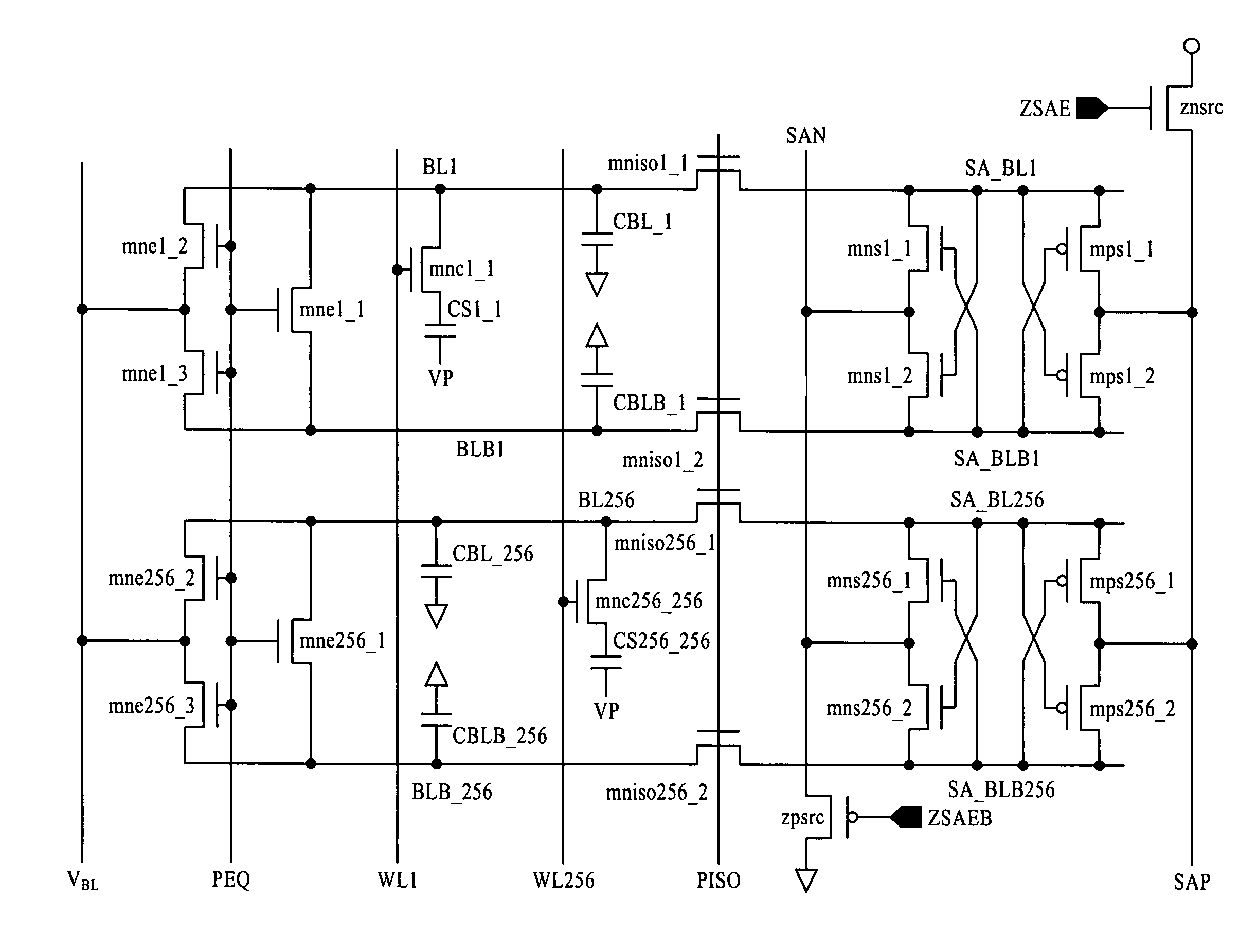
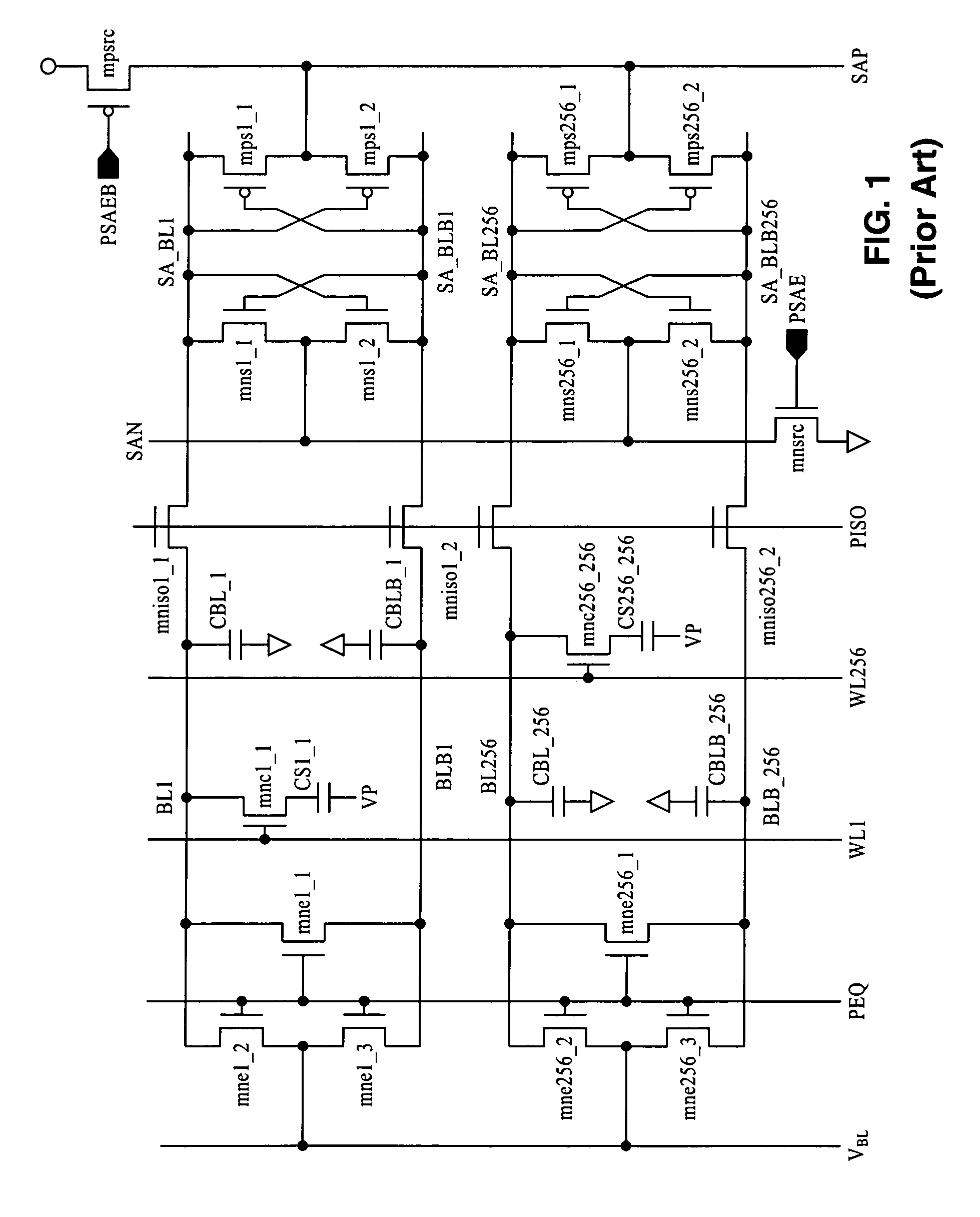
[0057]FIG. 4 illustrates an example of a new sense amplifier structure to suppress leakage current. This differs from conventional structures in the type of source transistors which are utilized and the mechanisms of driving the sense and restore lines. In the conventional DRAM core of FIG. 1, a drain with PMOS source transistor mpsrc is connected to a source of PMOS transistors mps1_1 and mps1_2, and a drain of NMOS source transistor mnsrc is connected to a source of NMOS transistors mns1_1 and mns1_2. This form of latch-drain combin...


PUM


Abstract

Circuits and methods are described for reducing leakage current and speeding access within dynamic random access memory circuit devices. A number of beneficial aspects are described. A circuit is described for an enhanced sense amplifier utilizing complementary drain transistors coupled to the sense or restore signals and driven by gate voltages which extend outside of the voltage range between VSS and VDD. The drain transistors are self reverse-biased in a standby mode. A method is also described for reducing leaking in non-complementary sense amplifiers by modifying the sense and restore gate voltages. Another aspect is a new negative word line method utilizing stacked pull-down transistors and a multi-step control circuit. In addition a level shifter scheme is described for preventing unwanted current flow between voltage sources while discharging control signal PX.

Description

CROSS-REFERENCE TO RELATED APPLICATIONS[0001]This application claims priority from U.S. provisional application Ser. No. 60 / 500,662 filed on Sep. 5, 2003, which is incorporated herein by reference.STATEMENT REGARDING FEDERALLY SPONSORED RESEARCH OR DEVELOPMENT[0002]Not ApplicableNOTICE OF MATERIAL SUBJECT TO COPYRIGHT PROTECTION[0003]A portion of the material in this patent document is subject to copyright protection under the copyright laws of the United States and of other countries. The owner of the copyright rights has no objection to the facsimile reproduction by anyone of the patent document or the patent disclosure, as it appears in the United States Patent and Trademark Office publicly available file or records, but otherwise reserves all copyright rights whatsoever. The copyright owner does not hereby waive any of its rights to have this patent document maintained in secrecy, including without limitation its rights pursuant to 37 C.F.R. § 1.14.BACKGROUND OF THE INVENTION[00...

Claims


Application Information

Patent Timeline
Patent Type & Authority Patents(United States)
IPC IPC(8): G11C11/24G11CG11C7/00G11C7/02G11C7/08G11C8/08G11C11/408G11C11/4091
CPCG11C7/02G11C7/065G11C7/08G11C7/12G11C8/08G11C11/4085G11C11/4091G11C11/4094G11C11/4074G11C2207/2227G11C2207/005
Inventor CHOI, MYUNG CHAN
Owner ZMOS TECH
Why Eureka
Try Eureka