Apparatus for fabricating soot preform for optical fiber

a technology of optical fiber and soot preform, which is applied in the direction of glass deposition burners, instruments, furniture, etc., can solve the problems of apparatus being difficult to clean, eroded upper room, and apparatus being more difficult to clean, so as to reduce bubbles and impurities, increase the exhausting efficiency of glass particles, and stable optical characteristics

Inactive Publication Date: 2006-08-01
SHIN ETSU CHEM IND CO LTD
View PDF1 Cites 8 Cited by
  • Summary
  • Abstract
  • Description
  • Claims
  • Application Information

AI Technical Summary

Benefits of technology

[0022]According to the foregoing description, an object of this invention is to provide an apparatus for fabricating a soot preform for an optical fiber by the VAD process. The apparatus can increase an exhausting efficiency of the stray glass particles and reduce bubbles and impurities in the resulting preform. Accordingly, using the apparatus, a soot preform for an optical fiber having stable optical characteristics along the lengthwise of the soot preform is obtained.

Problems solved by technology

Therefore, the upper room is eroded if the upper room is made of metals.
Even if the upper room is made of erosion-resistant materials, the apparatus is difficult to clean up after the preform fabricating process is finished.
Furthermore, the stray glass particles adhere to the hydrochloric acid-wet inner walls of the reaction room, resulting in that the apparatus is still more difficult to clean up.
Then, in the subsequent glassification process, the tree-like protrusions are formed on the surface of the soot preform, causing difficulty in measuring the distribution of refraction index.
In general, for avoiding foregoing issues, a downward gas flow from the top of the upper room to the reaction chamber is used, thereby preventing the stray glass particles from adhering and accumulating on the walls of the upper room to a degree, but cannot this could not prevent the particles from adhering and accumulating to the ceiling and the walls of the reaction chamber.
In the conventional methods, in the post stage of the fabrication of the soot preform, flakes of the glass particles adhered or accumulated on the inner walls of the reaction chamber get detached from the walls and fell, stirring up the glass particles, some of which fell on the soot preform, causing that bubbles and impurities are formed in the glassified soot preform.
However, this method causes the gas flow in the reaction chamber to be more turbulent, and the flame of the core burner, whose gas flow rate is relative low, is seriously disturbed.
As a result, the distribution of refraction index of the soot preform in the length-wise direction becomes uneven.
However, because the reaction chamber is divided into two separated reaction chambers, the control of the exhausting pressure for each reaction chamber becomes difficult.
In addition, the glass particles generated during the core deposition tend to accumulate on the lower side face of the partition, leading to the same drawbacks described above.
However in an apparatus as this, the gas flow around the core burner becomes faster and more turbulent, thereby the core deposition is disturbed and an even distribution of refraction index in the lengthwise direction cannot be obtained.
However, it could not efficiently prevent the exhausting gases and the stray glass particles from entering the upper room.

Method used


Image

  • Apparatus for fabricating soot preform for optical fiber
  • Apparatus for fabricating soot preform for optical fiber
  • Apparatus for fabricating soot preform for optical fiber

Examples


embodiments

>

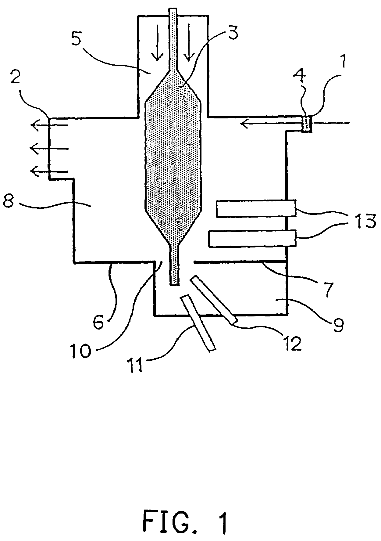
[0065]The manufacture apparatus as shown in FIG. 1 is designed to manufacture porous soot preforms by VAD method, and it comprises: a reaction furnace including a cylindrical upper room 5 having a radius of 130 mm provided on top of a substantially cubic reaction chamber, which has sides of about 500 mm, and being so designed that the center of the ceiling of the reaction chamber is coincidental with the center line of the cylindrical upper room 5; and a rotary shaft (not shown), whose rotation axis is coincidental with the central axis of the upper room 5, and which is capable of freely moving vertically. As shown schematically in FIG. 1, a gas-supplying inlet 1, a slit of 480 mm in length and 15 mm in width, is made in a vertical wall having burners 13 equipped thereon, at a location 5 mm beneath a ceiling of the reaction chamber, and a gas-exhausting outlet 2, 480 mm in length and 200 mm in width, is made in a wall opposite the gas-supplying inlet 1, at a location 5 mm beneath t...


PUM

PropertyMeasurementUnit
velocityaaaaaaaaaa
velocityaaaaaaaaaa
velocityaaaaaaaaaa

Abstract

An apparatus for fabricating a soot preform for an optical fiber. The soot preform is fabricated by depositing glass particles on a starting rod capable of being rotated and pulled up. The apparatus comprises elements as follows. A reaction chamber is used for depositing the glass particles on the starting rod. An upper room is located above the reaction chamber for receiving the soot preform formed in the upper portion of the reaction chamber. At least one core burner is installed in the reaction chamber. A gas-supplying inlet is located in the top part of the sidewall of the reaction chamber closest to burner(s), and a gas-exhausting outlet is located in the top part of another sidewall opposite to the gas-supplying inlet. In addition, at least one cladding burner is installed in the reaction chamber. Thus, the exhausting efficiency for the stray glass particles is increased and the bubbles and impurities in the resulting preform are reduced such that the optical property in the lengthwise direction is stable.

Description

CROSS-REFERENCE TO RELATED APPLICATION[0001]This application is a divisional application of, and claims the priority benefit of, U.S. application Ser. No 09 / 974,929 filed on Oct. 10, 2001BACKGROUND OF THE INVENTION[0002]1. Field of the Invention[0003]This invention relates in general to an apparatus for fabricating a soot preform for an optical fiber, and more specifically relates to an apparatus for stably fabricating a high-quality soot preform for an optical fiber by vapor-phase axial deposition.[0004]2. Description of Related Art[0005]Vapor-phase axial deposition (VAD) is a well-known process for fabricating a fiber preform nowadays. A starting rod is installed on a shaft capable of being rotated and shifted vertically into and out of a reaction chamber. Glass particles generated by a core burner and a cladding burner in the reaction chamber are deposited on the front end of the starting rod, thereby a porous soot preform (soot preform, hereinafter) consisting of a core and a cl...

Claims


Application Information

Patent Timeline
Patent Type & Authority Patents(United States)
IPC IPC(8): C03B37/018C03B37/014G02B6/00
CPCC03B37/01406C03B2207/54G02B6/00
Inventor INOUE, DAIOGINO, GOOTOSAKA, TETSUYASHIMADA, TADAKATSUHIRASAWA, HIDEO
Owner SHIN ETSU CHEM IND CO LTD
Why Eureka
Try Eureka