Resin intake manifold

a technology of intake manifold and resin, which is applied in the direction of intake silencers for fuel, combustion air/fuel air treatment, machines/engines, etc., can solve the problems of bolt dropping from the gap formed between the intake pipes, reducing strength, and concentrated stress, so as to improve the operation of the nuts or the like, improve productivity, and improve the effect of amide group concentration

Inactive Publication Date: 2006-08-01
AISAN IND CO LTD
View PDF11 Cites 24 Cited by
  • Summary
  • Abstract
  • Description
  • Claims
  • Application Information

AI Technical Summary

Benefits of technology

[0035]In accordance with the present invention, there is provided a resin intake manifold provided with a surge tank portion, an even number of intake pipes branched from the surge tank portion so as to be connected to respective cylinders, and mounting flange portions formed in leading end portions of the intake pipes and connected to a cylinder head, wherein a connection between the mounting flange portions and the cylinder head is achieved by a screw connection, the mounting flange portions are provided with bolt holes, and a pair of ribs having a gap between a pair of ribs so as to prevent the screw member from falling off are formed between opposing walls of the intake pipes.
[0036]Since a pair of ribs are provided between the opposing walls of the intake pipes so as to prevent the screw member from falling off, there is no risk that a nut falls off, and a screw fastening operability of the nut or the like is improved. Further, no water stays owing to the gap formed between the ribs for preventing the nut from falling off, and the stress crack is hard to be generated due to the hygroscopic swelling or the calcium chloride.
[0037]In the structure mentioned above, the structure may be made such that the bolt holes provided in the mounting flange portions are arranged on a diagonal line with respect to the respective cylinder holes of the cylinder head, and a pair of ribs are formed in the opposing walls of the intake pipe in which the screw fastening is at a far side position. In accordance with this structure, the screw fastening operability is better, and an effect of the present invention is remarkable.
[0038]In the structure mentioned above, it is desirable that the gap between a pair of ribs is formed from the mounting flange portion toward the intake pipe and at least a terminal end wall of the gap between a pair of ribs is formed so as to be inclined in a die cutting direction of a female mold or so as to be over a back surface wall of the ribs. At a time of forming the base portion, the gap between a pair of ribs is short of undercut, the slide core for forming the gap between a pair of ribs is not required, and a productivity is improved.
[0039]In each of the structures mentioned above, it is desirable that a top surface of the rib for preventing the nut from falling off is formed in a shape corresponding to a water stream guide surface for guiding a water stream to the gap between a pair of ribs. The water is more rapidly discharged, and the hygroscopic swelling and the stress crack are harder to be generated.
[0040]It is desirable that the molding material of the intake manifold is normally constituted by a polyamide in which a polyamide density reinforced by an inorganic fiber is equal to or more than an approximately polyamide 6. Since the material has a high amide group concentration and is easy to generate the hygroscopic swelling and the stress crack, the operation and effect of the present invention are remarkable.

Problems solved by technology

However, in accordance with the prior art mentioned above, since the resonant chamber is formed by using a flat member, there is a problem that in the case that a great positive pressure is rapidly applied to an inner side of the surge tank due to a back fire or the like, a stress is concentrated and a strength is lowered.
Further, in the case that the thickness of the wall portion in the surge tank is increased, since thickening a side of an inner wall portion of the wall portion reduces a capacity of the surge tank, this structure is not preferable.
At a time of the fastening work of the nut, there is a risk that the bolt drops from a gap formed between the intake pipes.
In particular, in the case of mounting at the far side position, a mounting workability is not good, and there is a risk that the bolt drops during the mounting work.
In the case that the intake manifold is formed by a resin material with high water absorbability such as a polyamide 6 or the like, there is a risk that the intake manifold hygroscopic swells.
Further, in the case of being in contact with a snow melting agent (a calcium chloride solution) for a long time, there is a risk that a stress crack caused by a metal salt is generated.

Method used


Image

  • Resin intake manifold
  • Resin intake manifold
  • Resin intake manifold

Examples


Embodiment Construction

[0076](i) Embodiment of First Aspect of the Present Invention

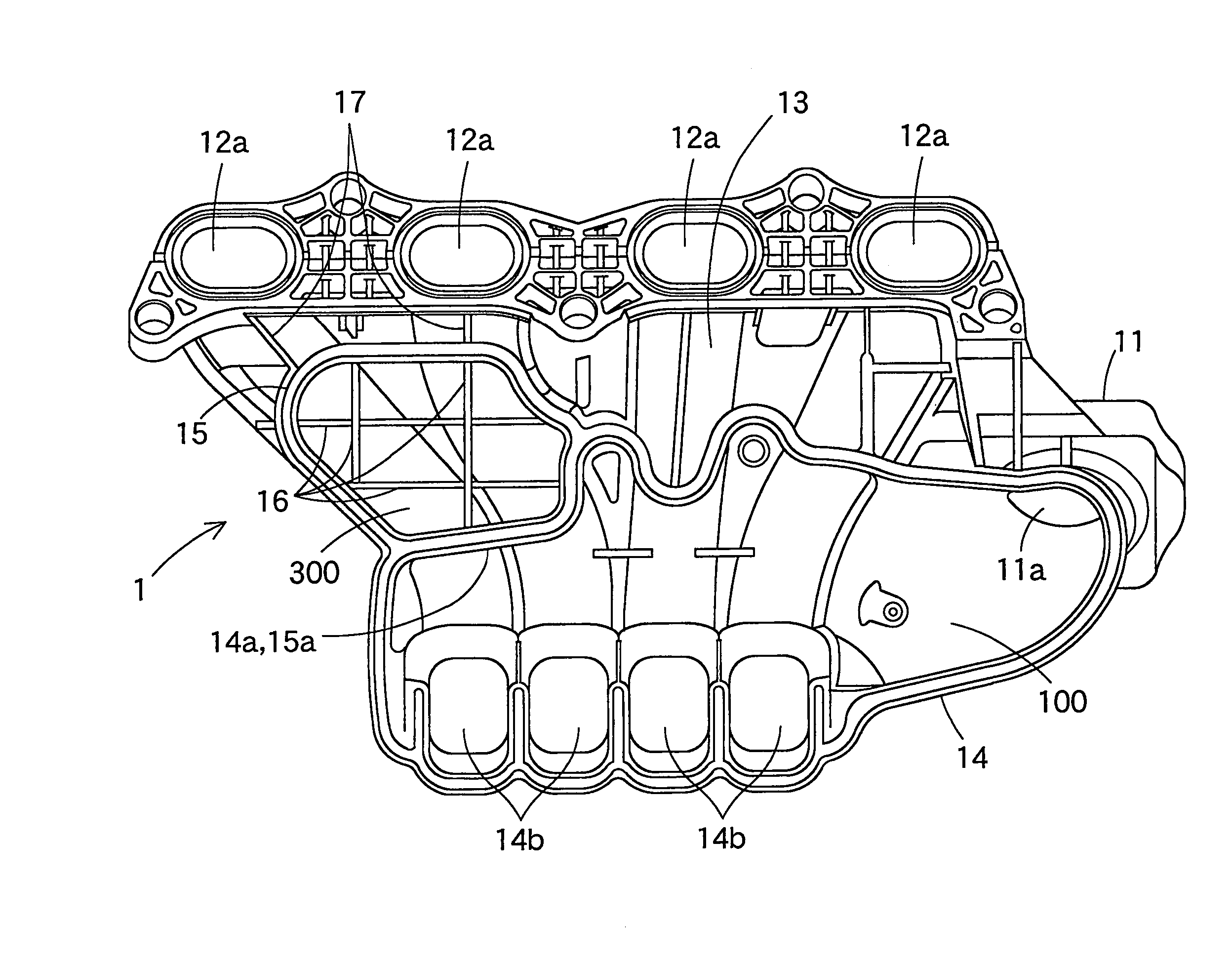
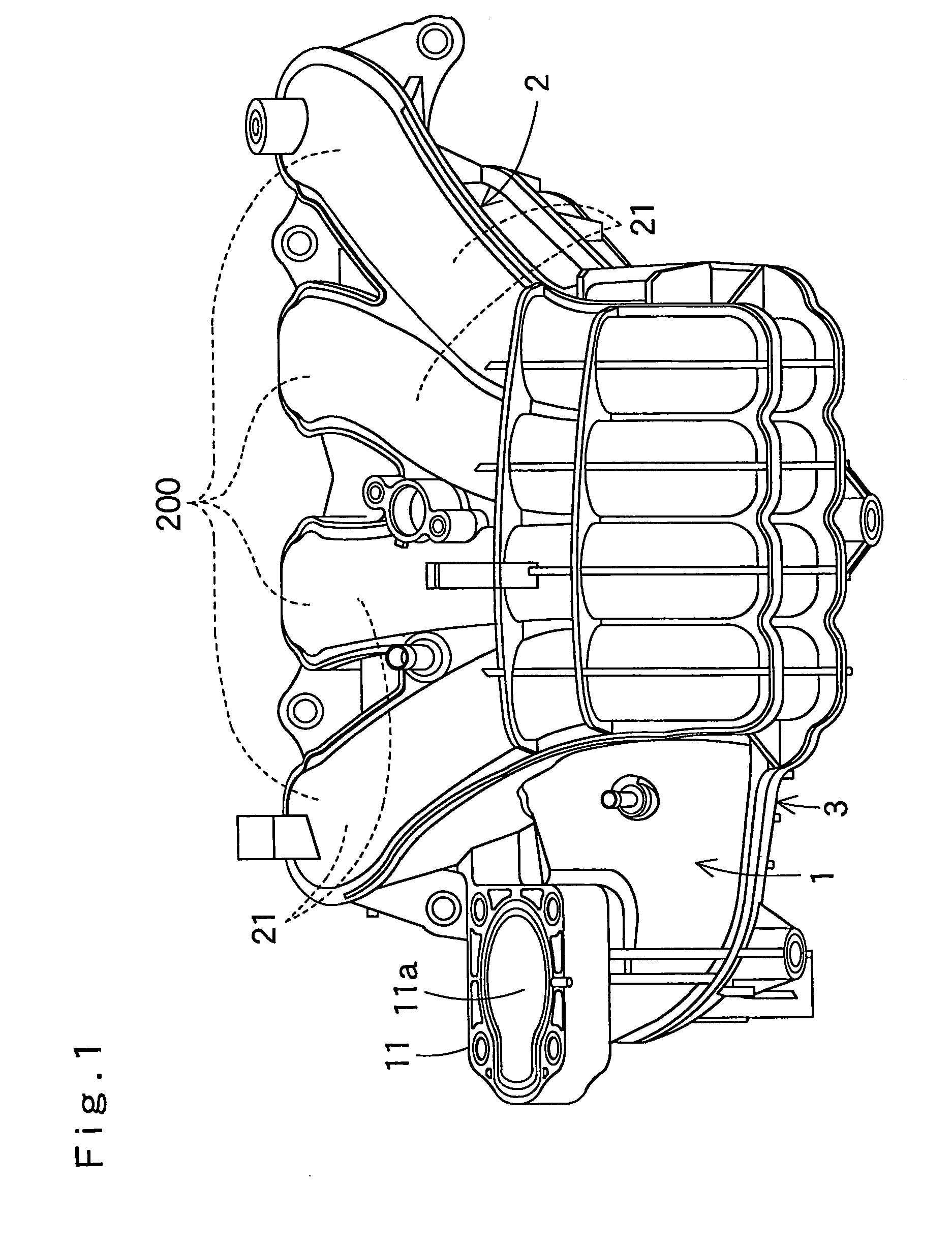
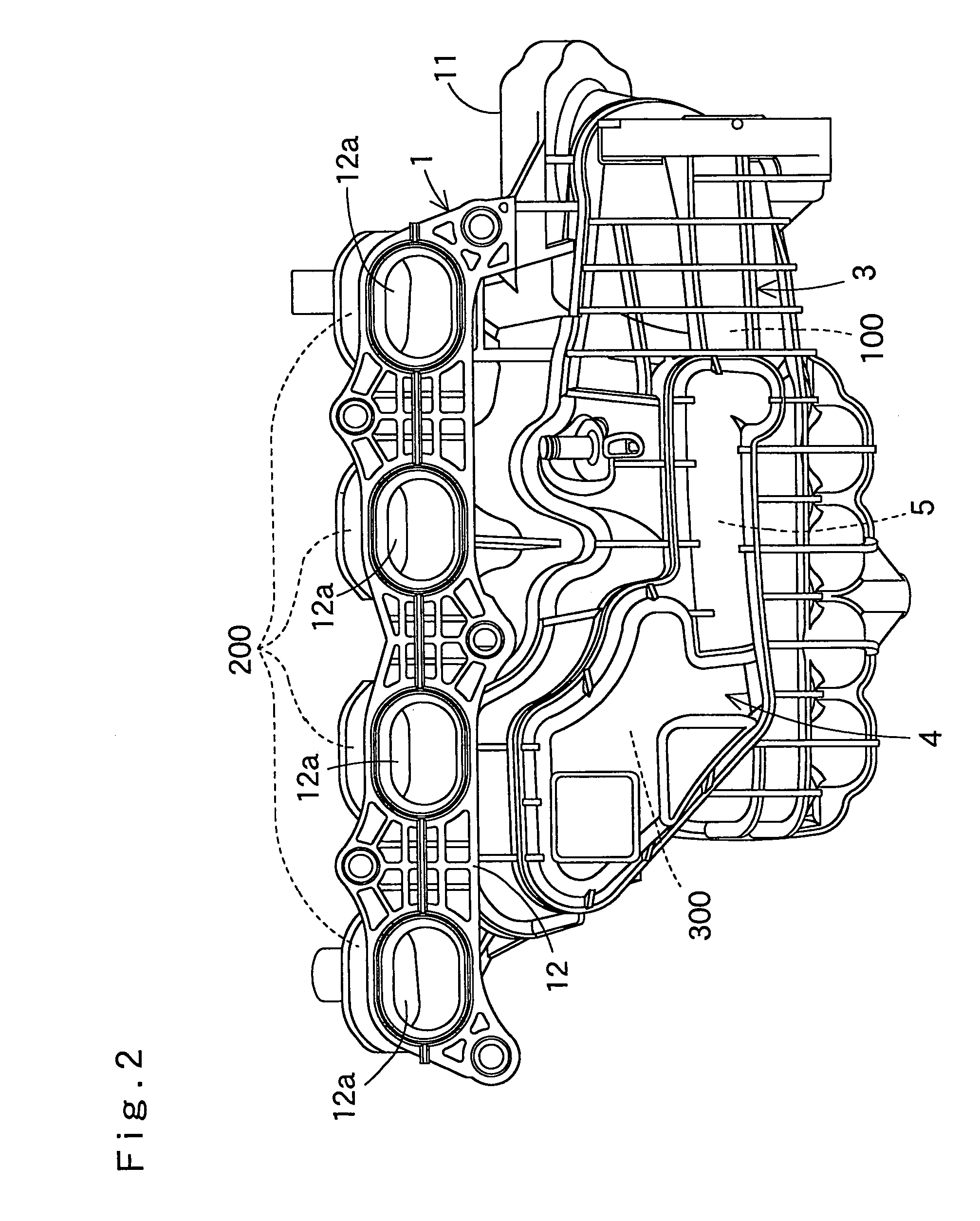
[0077]FIGS. 1 to 4 show a resin intake manifold in accordance with an embodiment of a first aspect of the present invention, in which FIG. 1 is a front elevational view, FIG. 2 is a back elevational view, FIG. 3 is a right side elevational view and FIG. 4 is a left side elevational view. FIGS. 5 to 8 show a base member of the intake manifold, in which FIG. 5 is a front elevational view, FIG. 6 is a back elevational view, FIG. 7 is a right side elevational view and FIG. 8 is a left side elevational view. FIGS. 9 to 14 show a tank lower surface wall and resonator peripheral wall member welded to a lower surface side of the base member, in which FIG. 9 is a front elevational view, FIG. 10 is a back elevational view, FIG. 11 is a plan view, FIG. 12 is a bottom elevational view, FIG. 13 is a right side elevational view, and FIG. 14 is a left side elevational view. FIGS. 15 to 19 show a lower cover member welded to a front surfa...


PUM

PropertyMeasurementUnit
heightaaaaaaaaaa
heightaaaaaaaaaa
angleaaaaaaaaaa

Abstract

A resin intake manifold is provided with an integrally formed base member. The base member has a U-shaped curved distribution passage lower surface wall portion, an engine mounting flange portion formed in one end of the distribution passage lower surface wall portion, and a surge tank peripheral wall portion formed in another end and a lower surface side of the distribution passage lower surface wall portion. A resonator peripheral wall portion is integrally formed in a dead space in a lower surface side of the distribution passage lower surface wall portion and between the surge tank peripheral wall portion and the engine mounting flange portion. In accordance with the structure in which the wall itself constituting the resonator is formed by the structure member, it is possible to structure the resonator without enlarging a size of the intake manifold and without lowering the strength.

Description

CROSS-REFERENCE TO RELATED APPLICATION[0001]The present application claims priority to Japanese patent applications No. 2003-102801 filed Apr. 7, 2003, No. 2003-104306 filed Apr. 8, 2003, and No. 2003-104421 filed April 8, the entirety of each is hereby incorporated into the present application by this reference.BACKGROUND OF THE INVENTION[0002](1) Field of the Invention[0003]The present invention relates to a resin intake manifold, and more particularly to a resin intake manifold which is arranged between a cylinder head of an engine and a throttle body.[0004](2) Description of the Prior Art[0005](i) Prior Art Relevant to First Aspect of the Present Invention[0006]In conventional, as a resin intake manifold, there has been known a structure in which a resonator serving as a resonant chamber is independently provided in a dead space within a surge tank, for the purpose of effectively utilizing the dead space (refer to, for example, Japanese Unexamined Patent Publication No. 11-22998...

Claims


Application Information

Patent Timeline
Patent Type & Authority Patents(United States)
IPC IPC(8): F02M35/10B29C65/00F02M35/12
CPCF02M35/10039F02M35/10078F02M35/10295F02M35/1288F02M35/10347F02M35/1036F02M35/1255F02M35/1277F02M35/1283F02M35/10321B29C66/322B29L2031/7492F02M35/10111
Inventor TANIKAWA, HIRONORIFUJIMORI, MAKOTOAIKI, KAZUHIRO
Owner AISAN IND CO LTD
Why Eureka
Try Eureka