
Pipe tapping apparatus

a technology of tapping apparatus and pipe, which is applied in mechanical apparatus, branching pipes, transportation and packaging, etc., can solve the problems of imposing huge costs on the ground when installing main pipes, and achieve the effect of enhancing economic efficiency and easy coupleing of sub-pipes

Active Publication Date: 2006-08-01
ISCO INDS +1
View PDF7 Cites 13 Cited by
  • Summary
  • Abstract
  • Description
  • Claims
  • Application Information

AI Technical Summary

Benefits of technology

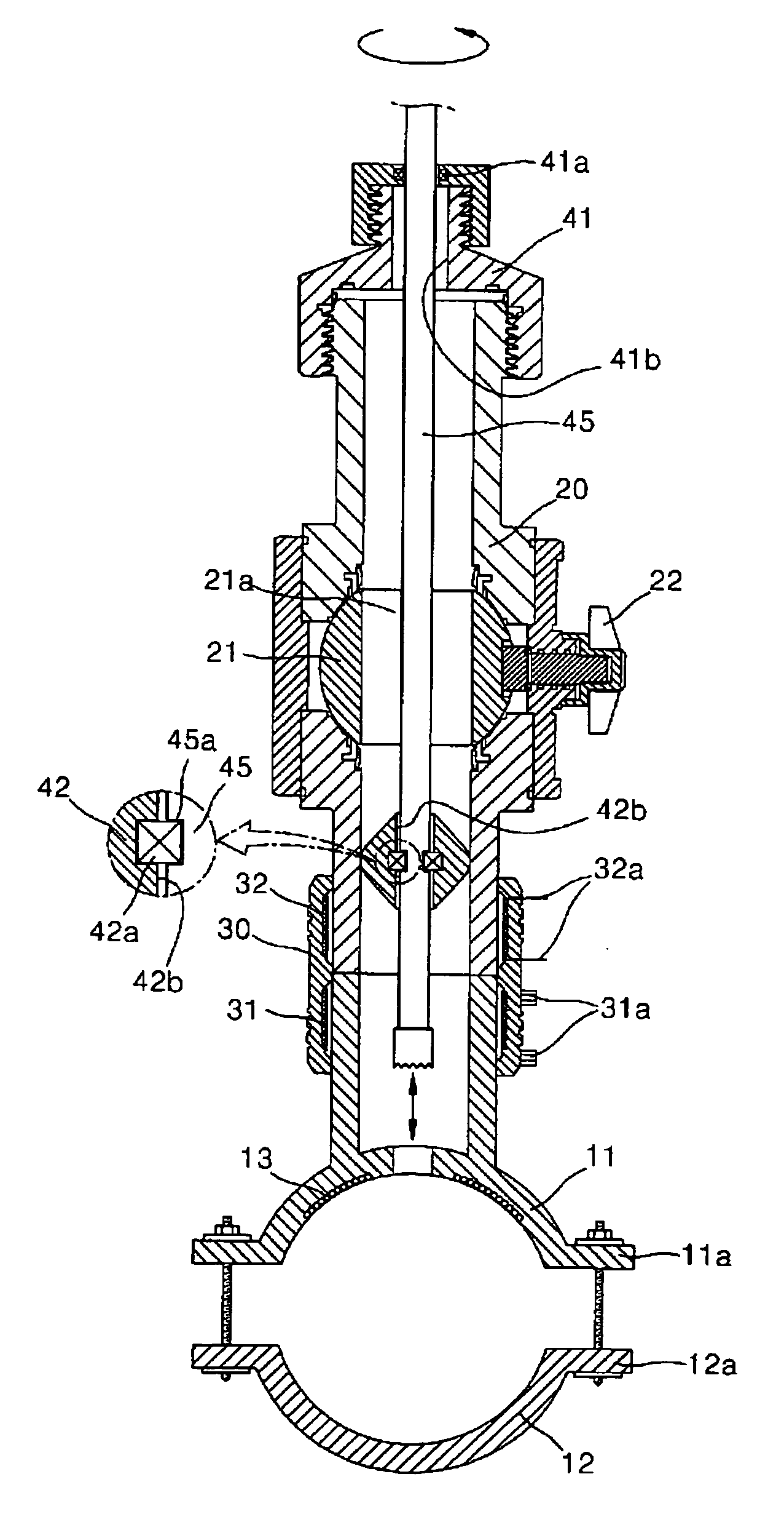
"The present invention provides a pipe tapping apparatus that allows for easy coupling of a sub-pipe to an existing main pipe through an electric heat-welding process and a tapping process using a cutting drill. The apparatus includes a base pipe, a coupling pipe, an electric heat-welding pipe, and a positioning unit for tapping the main pipe. The apparatus also includes a main heating wire and a second positioning unit for welding the coupling pipe to the base pipe. The apparatus provides a module system that allows for welding the inner surface of the coupling pipe to the outer surface of the base pipe using the second heating wire. The technical effects of the invention include improved economical efficiency and simplified construction processes in field building sites."

Problems solved by technology

However, huge costs are incurred when installing the main pipes in the ground.
Therefore, when additional buildings or factories are built around the existing structures, if additional main pipes for the additional buildings or factories are required to be installed in the ground, it is very expensive.

Method used


Image

  • Pipe tapping apparatus
  • Pipe tapping apparatus
  • Pipe tapping apparatus

Examples


Embodiment Construction

[0017]Hereinafter, embodiments of the present invention will be described in detail with reference to the attached drawings.

[0018]Reference now should be made to the drawings, in which the same reference numerals are used throughout the different drawings to designate the same or similar components.

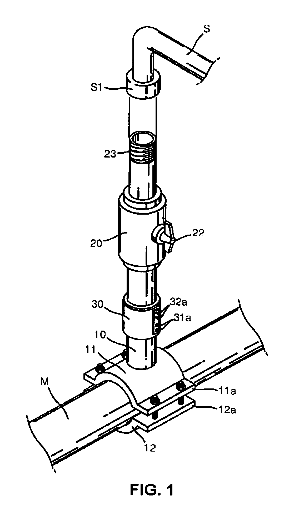
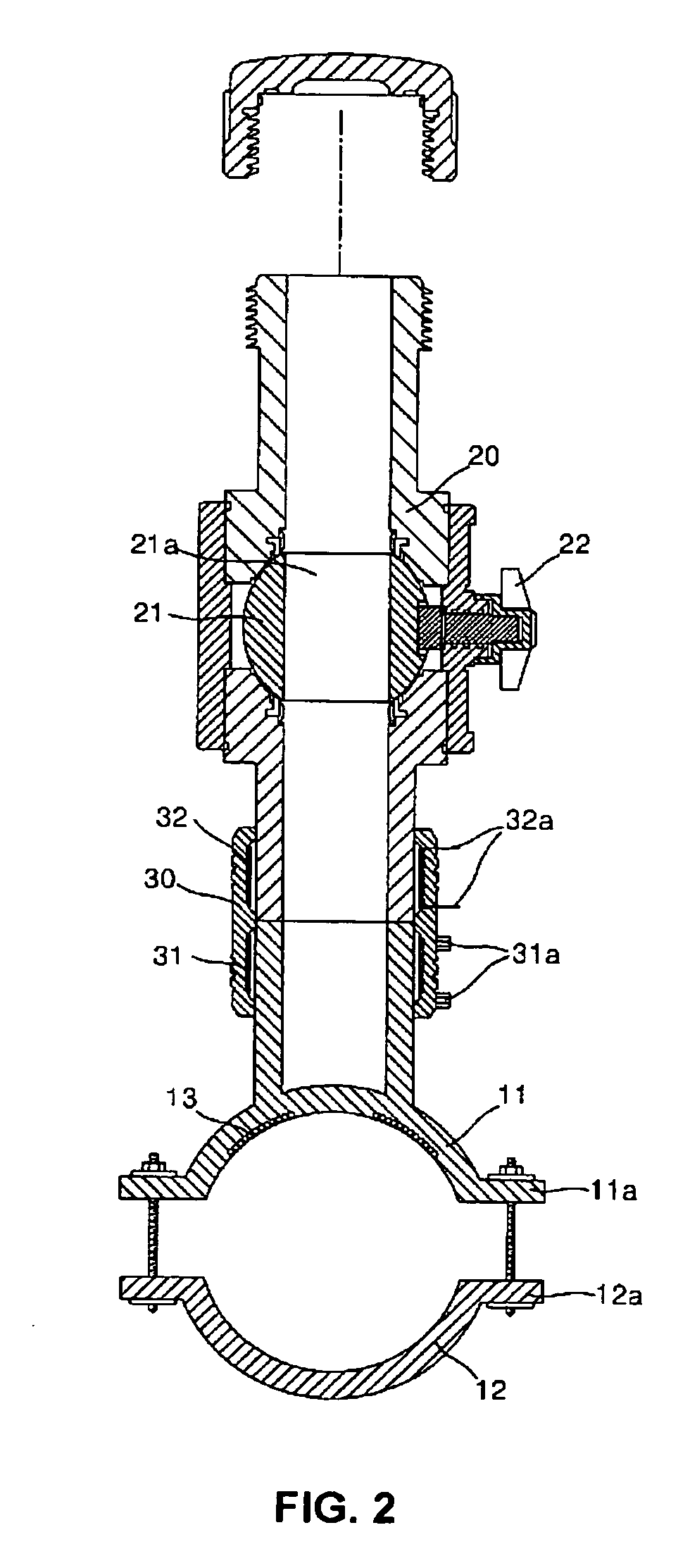
[0019]FIG. 1 is a perspective view of a pipe tapping apparatus, according to an embodiment of the present invention. FIG. 2 is a longitudinal sectional view of the pipe tapping apparatus of FIG. 1.

[0020]As shown in FIGS. 1 and 2, the pipe tapping apparatus of the present invention couples a sub-pipe (S), which extends to a household or building using gas or city water (hereinafter, referred to simply as fluid), to an outer surface of a main-pipe (M) which is arrayed in the ground to pass the fluid through the main-pipe (M).

[0021]The pipe tapping apparatus of the present invention includes a base pipe 10 which is coupled at a predetermined position to the outer surface of the main-pipe (M)...


PUM


Abstract

The present invention provides a pipe tapping apparatus to couple new pipes to an existing pipe. The pipe tapping apparatus includes a base pipe, having a saddle-shaped socket part to be in close contact with the main pipe to pass a fluid therein; and a bending part coupled to the saddle-shaped socket part. The pipe tapping apparatus further includes a coupling pipe to be coupled to the sub-pipe extending to a predetermined place in which the supplied fluid is used, with a ball valve provided in the coupling pipe to control the flow of fluid passing through the coupling pipe. The pipe tapping apparatus further includes an electric heat-welding pipe to couple the coupling pipe to the base pipe. The electric heat-welding pipe has a first heating wire which is provided in the electric heat-welding pipe to weld the electric heat-welding pipe to the base pipe, and a second heating wire which is provided in the electric heat-welding pipe to integrate the coupling pipe with the electric heat-welding pipe. The pipe tapping apparatus further includes a first positioning unit which is removably coupled to an end of the coupling pipe, with a first through hole provided in the center of the first positioning unit, thus guiding a process of tapping the main pipe using the cutting drill passing through the first through hole of the first positioning unit.

Description

[0001]This application claims priority benefits from Korean Patent Application No. 10-2004-0061182 filed Aug. 3, 2004.BACKGROUND OF THE INVENTION[0002]1. Field of the Invention[0003]The present invention relates generally to pipe tapping apparatuses, and more particularly, to a pipe tapping apparatus to couple new pipes to an existing pipe.[0004]2. Description of the Related Art[0005]Generally, gas pipes and city water pipes (hereinafter, referred to simply as main pipes) are arranged in the ground. The above-mentioned main pipes supply gas or water to structures, such as households, offices and factories, etc. Therefore, when the above-mentioned structures are constructed, the main pipes are simultaneously arranged in the ground around the structures. To arrange the main pipes in the ground, the ground is dug over a distance of several kilometers. Thereafter, the main pipes having lengths of several kilometers are placed in troughs in the ground prior to being covered with soil. Th...

Claims


Application Information

Patent Timeline
Patent Type & Authority Patents(United States)
IPC IPC(8): F16K43/00
CPCF16L41/06F16L41/16F16L41/084Y10T137/6123F16L41/04
Inventor KIM, YOUNG SIKDEASON, MICHAEL T.
Owner ISCO INDS
Learn More