Electronic estrus detection device

a detection device and estrus technology, applied in medical science, ovulation diagnostics, vaccination/ovulation, etc., can solve the problems of increased ovulation, increased ovulation, and increased ovulation frequency, so as to facilitate water resistance and optimal visible signal observation

Inactive Publication Date: 2006-08-01
COWCHIPS
View PDF11 Cites 39 Cited by
  • Summary
  • Abstract
  • Description
  • Claims
  • Application Information

AI Technical Summary

Benefits of technology

[0020]In a preferred embodiment, the electronic device is encased and sealed in a clear housing facilitating water resistance and optimal visible signal observation from a variety of angles or vantage points. In an alternate embodiment, the power source portion of the device is encased in its own sealed housing adapted to functionally integrate with the remainder of the device, thereby facilitating part removal and / or replacement.

Problems solved by technology

Estrus detection may be the most common and costly failure of breeding programs.
Inefficient detection of estrus results in lost lifetime milk yield in dairy cows, decreased number of calves born per lifetime, excessive days open, and increased reproductive culling (Walker et al.
However, prior attempts at detection of estrus in cattle have proven unsatisfactory.
However, implanted devices, subcutaneous or otherwise, present a number of issues, for example, surgical implantation of the device itself, retrieval of a failed device, retrieval of devices from culled animals, infection at the implantation site and rejection of the device.
Despite these attempts to detect estrus, none of the prior art satisfactorily solves the problem of how to reliably and efficiently detect estrus and / or the optimal breeding time.
Shortcomings found in the prior art include, for example, the detection of the onset of estrus rather than detection of estrus, the necessity of surgical procedures, and the necessity of complex and / or computer-based systems.
Such fully automated cow monitoring systems are expensive and inappropriate for use with, for example, small herds.

Method used


Image

  • Electronic estrus detection device
  • Electronic estrus detection device
  • Electronic estrus detection device

Examples


Embodiment Construction

[0036]It is to be understood that both the foregoing general description and the following detailed description are exemplary and explanatory only and are not restrictive of the invention as claimed.

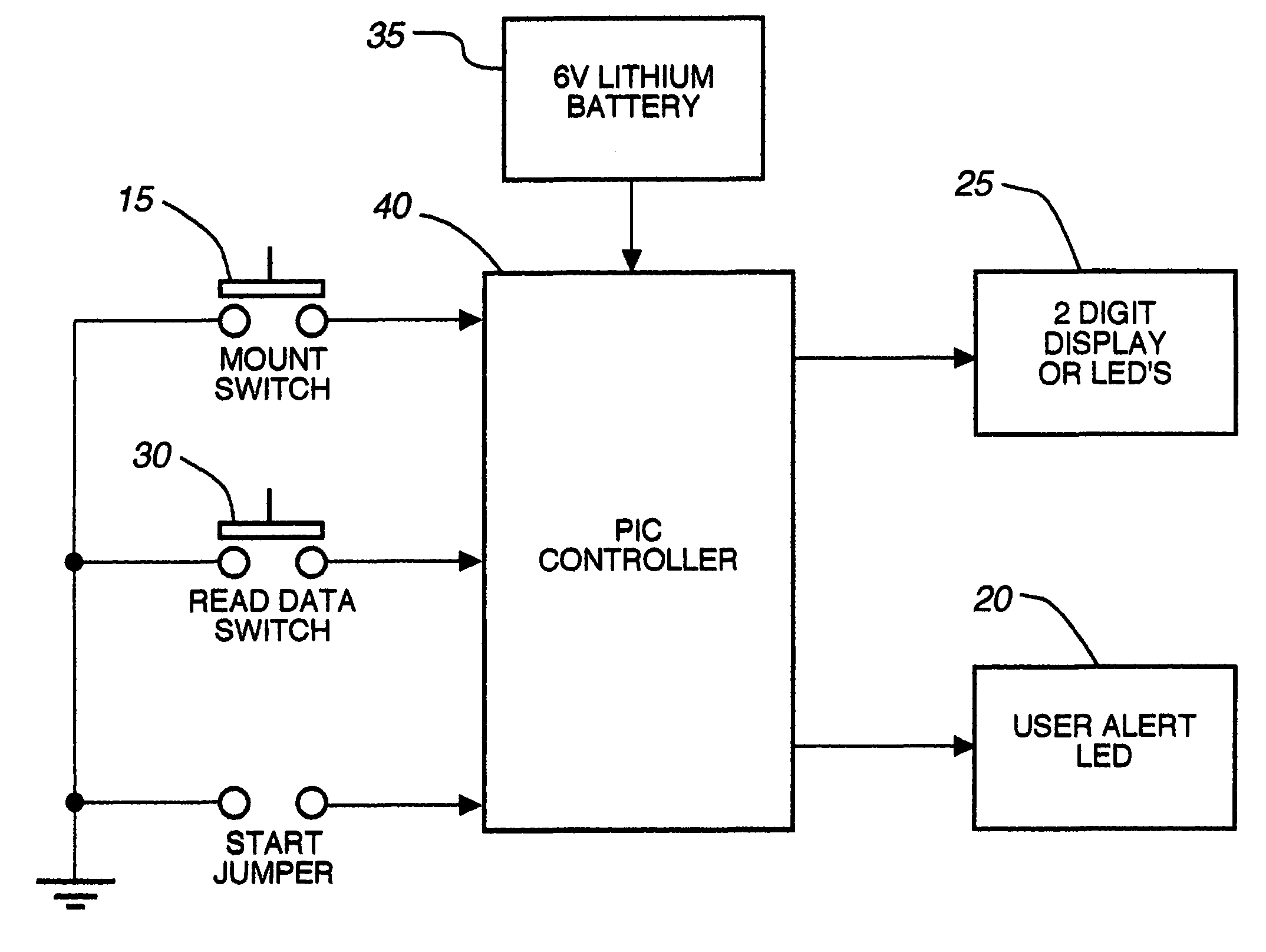
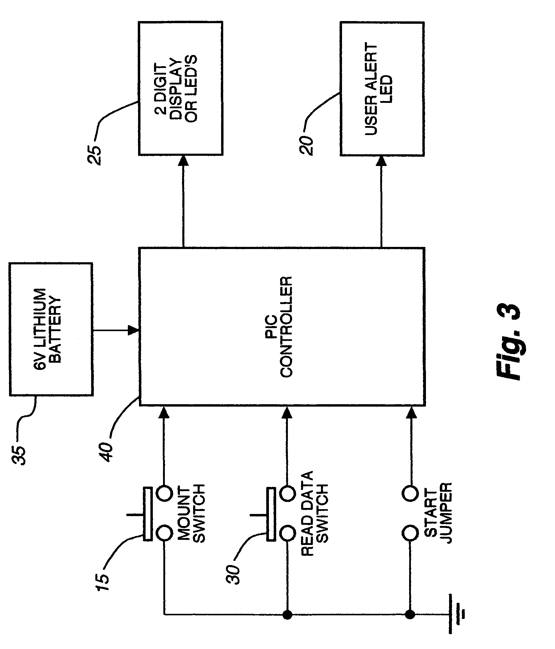
[0037]The present invention provides an electronic estrus detection device useful for optimal timing of insemination in cattle by determination and counting of mounting activity related to the estrus cycle. It is recognized by those skilled in the art that a broad range of estrus detection devices may be practiced in accordance with the presently disclosed invention.

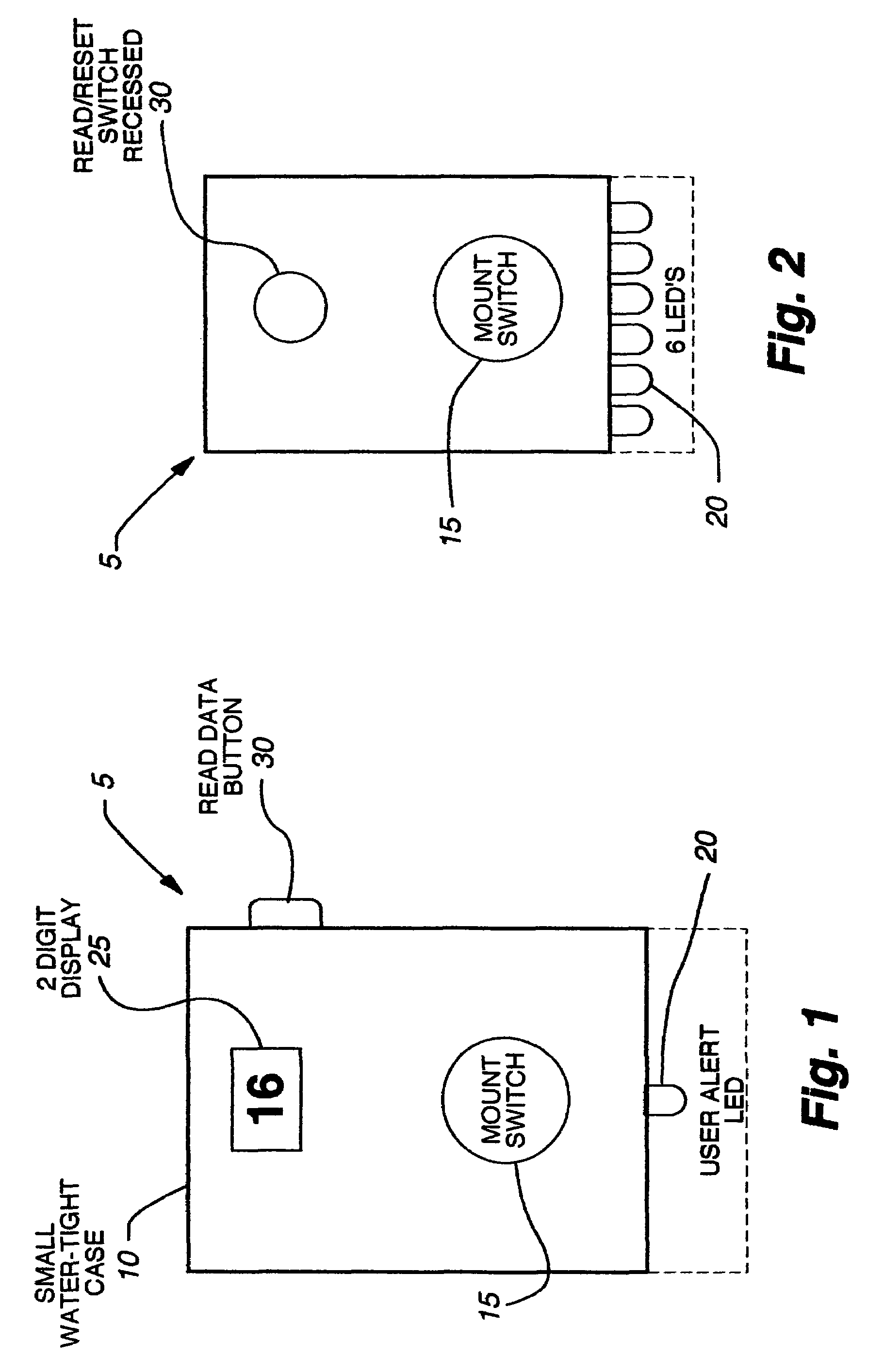
[0038]Moving to FIG. 1, shown is a detailed external, top view of first preferred embodiment. A generally rectangular box shaped detection device 5. Said device provides six generally rectangular surfaces (see FIG. 5); a lower surface that rests generally horizontally against the tail head area of a cow, an opposite facing upper surface upon which a pressure sensitive switch and digital display are located, four generally ver...


PUM


Abstract

An electronic device for detecting estrus that may be affixed to the tail-head area of a cow is described. This device permits the accurate determination of optimal breeding time, natural or artificial, based on mounting activity. The device includes a water resistant housing, within which is contained the electronic portion of the device consisting of a controller means, a power means, an activation means, a read data means, and at least one display means; said device determining and subsequently indicating suspected and confirmed estrus based on an algorithm. The invention may be used, for example, with any non-human animal exhibiting standing heats and / or mounting behavior indicative of an estrus cycle for making mounting data determinations related to the estrus cycle and analyzing such data to determine optimal time to breed.

Description

RELEATED APPLICATIONS[0001]This application claims priority to provisional patent application U.S. Ser. No. 60 / 113,202, filed 22 Dec. 1998. The earlier filing date of this application is hereby claimed.FIELD OF THE INVENTION[0002]The present invention relates to the general field of estrus detection, and more specifically, to an electronic device for attachment to the posterior of a cow that counts and times mounts by other cows. This application, thus, describes an electronic device useful for determination of estrus, said device enabling, for example, an artificial insemination technician to appropriately determine the optimum time of insemination and / or breeding, thereby increasing number of pregnancies and reducing the number of open cows, and in turn, increasing milk and / or meat production.BACKGROUND AND PRIOR ART[0003]Animal husbandry technique advancement, including for example, computerized genetic selection and / or tracking and artificial insemination (AI) allows both dairy ...

Claims


Application Information

Patent Timeline
Patent Type & Authority Patents(United States)
IPC IPC(8): A61B10/00A61B17/43
CPCA61D17/002A01K29/005
Inventor CLAYCOMB, RODNEYCLARK, SCOTTEBBEN, THOMASKOCH, SHAWNOLSON, JAKE
Owner COWCHIPS
Why Eureka
Try Eureka