Method for thermal optimization

a technology of thermal optimization and optimization method, which is applied in the direction of electric controller, electric programme control, program control, etc., can solve the problems of only taking advantage of the full capacity of the robot, putting demands on the thermal load of the driving system, and affecting the operation of the engine and the driving devi

Inactive Publication Date: 2006-08-01
ABB (SCHWEIZ) AG
View PDF11 Cites 10 Cited by
  • Summary
  • Abstract
  • Description
  • Claims
  • Application Information

AI Technical Summary

Benefits of technology

[0015]However, it is common that the performances in some parts of the path are more important than the performance in other parts of the path. In one embodiment of the invention, the engine torque and / or or the engine number of revolutions and / or the currents of the driving devices are adjusted with different amounts in different parts of the movement path. By optimising different parts of the path by themselves, one can obtain a higher performance in selected critical parts of the path at the expense of the performance in other less critical parts of the path.
[0016]In one embodiment of the invention, at least one of the driving system parameters in at least one part of the movement path is adjusted and the driving system parameters are kept in at least one part of the path. This embodiment is especially advantageous in applications demanding maximum performance during one or several short periods of the path and where the path comprises one or several longer periods with a low demand on performance.

Problems solved by technology

When the robot is in operation, a heating of the engines and the driving devices takes place due to power losses arising from the electro-mechanical energy conversion.
Different applications put demands on the thermal load in the driving system, i.e. how large the power losses may be in the driving system.
This means that the full capacity of the robot is only taken advantage of in a small number of applications.

Method used


Image

  • Method for thermal optimization
  • Method for thermal optimization
  • Method for thermal optimization

Examples


Embodiment Construction

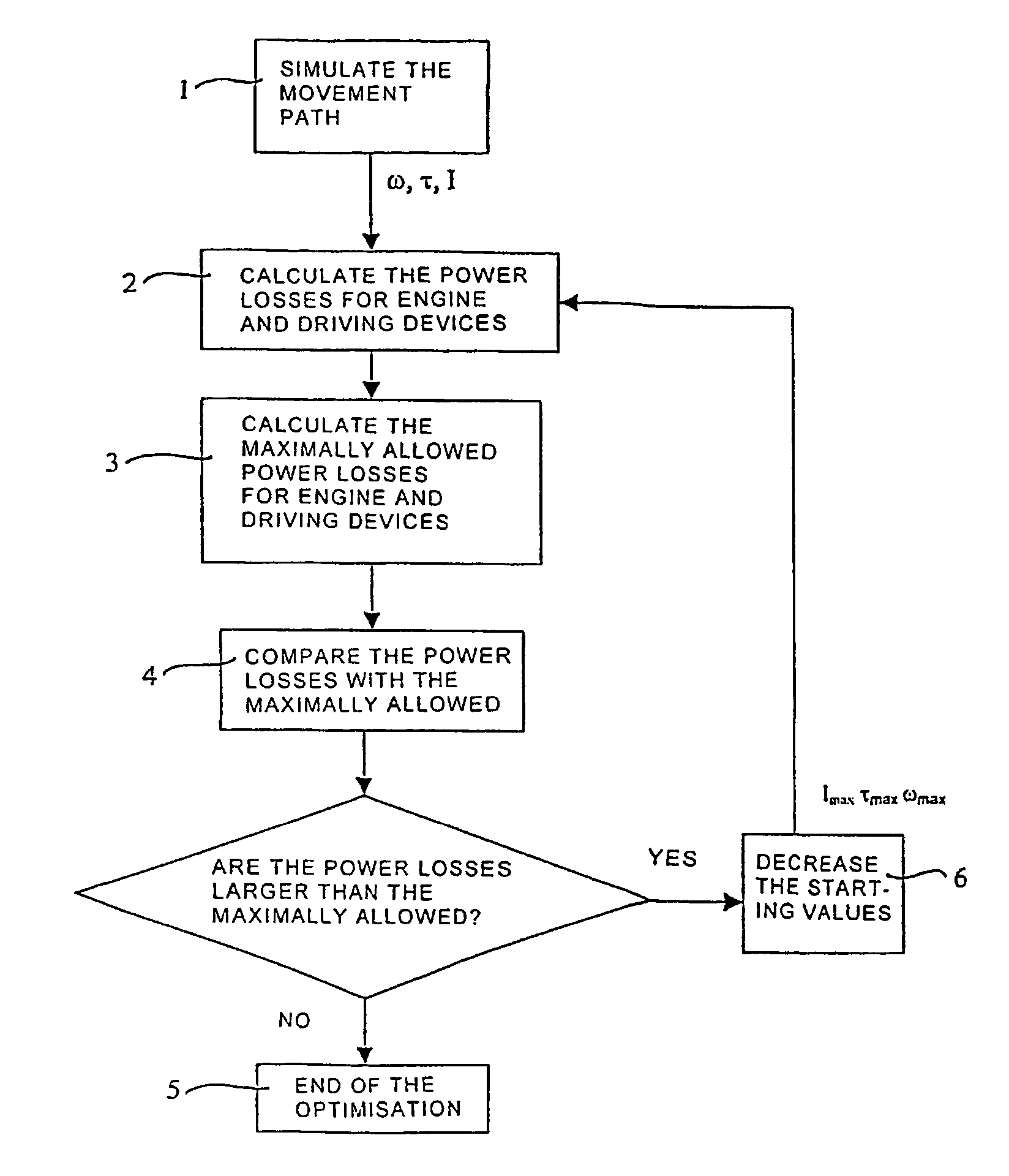
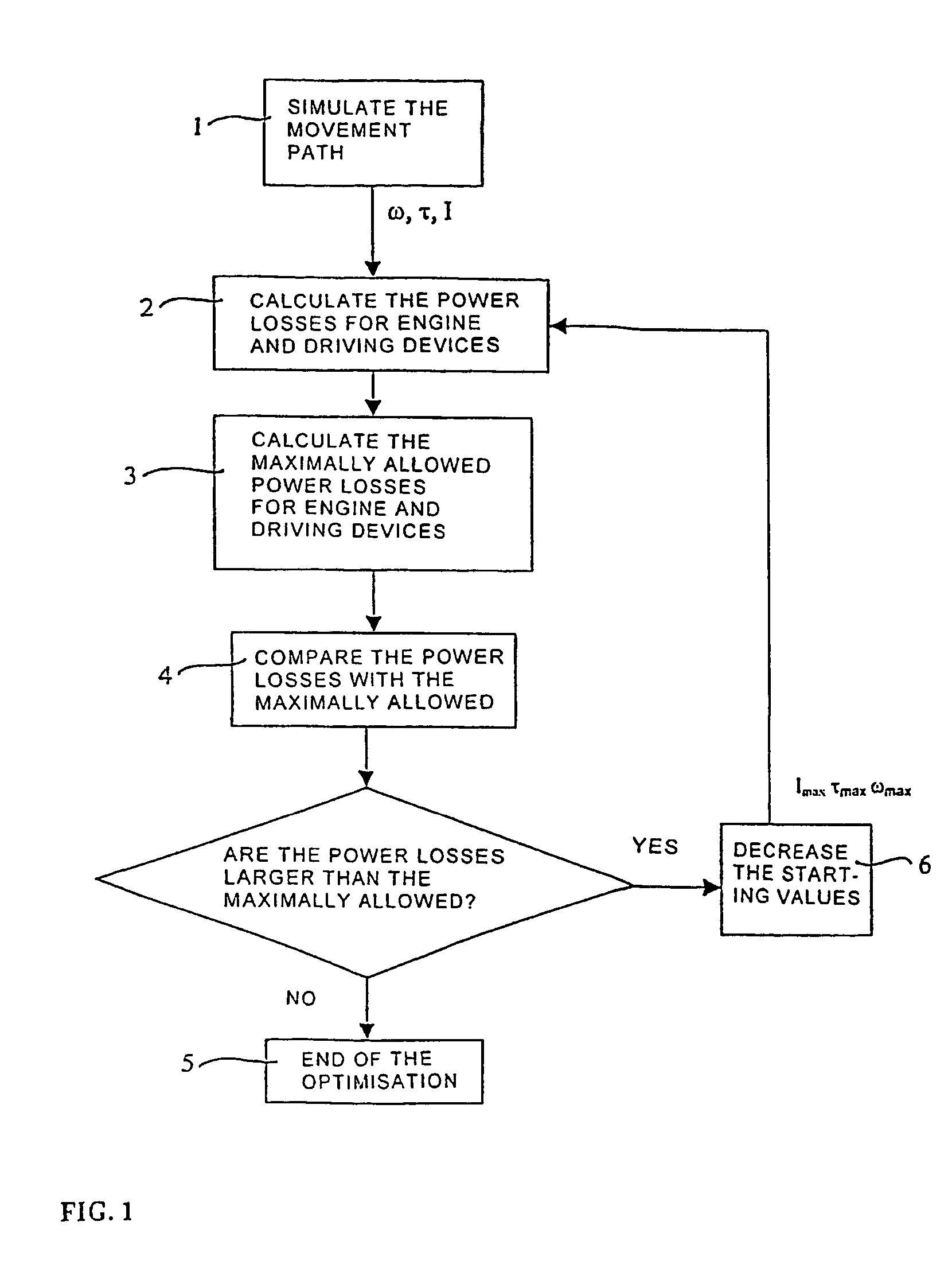
[0005]The object of the invention is to obtain a method for optimising the movement performance of a robot with respect to the power loss in the driving system of the robot.

[0006]Optimisation of the movement performance of a robot for a current movement path refers to an optimisation of the accelerations and velocities of the robot axes for the movement path. According to the method according to the invention, this optimisation takes place through adjustment of the accelerations and the velocities for the movement path until a maximal thermal utilisation of the driving system of the robot has been achieved. A maximal thermal utilisation refers to that the power loss in the driving system is as close to the maximally allowed power loss in the driving system as possible without exceeding it. Of course, there may be other limits except the thermal, for example electrical and mechanical limits, resulting in that it is not always possible to run the driving system close to its outermost ...


PUM


Abstract

Method for optimizing the movement performance of an industrial robot for a current movement path with respect to thermal load on the driving system of the robot, wherein the method comprises the following steps: for at least one component in the driving system, the thermal load is calculated for the whole or parts of the movement path if the calculated thermal load is compared with a maximally allowed load for the component; and dependent on said comparison, a course of accelerations and velocities for the current movement path are adjusted.

Description

TECHNICAL FIELD AND PRIOR ART[0001]The present invention relates to a method for optimising the movement performance of an industrial robot for a current movement path with respect to power losses in the driving system of the robot. The invention also relates to a computer program product which, when run by a processor, controls it so that the steps of the method are executed.[0002]An industrial robot comprises a number of arms, which are rotatable relative to each other around a number of movement axes. The velocities and the accelerations of the axes are controlled by the control system of the robot, which gives control signals to the driving system of the robot. The driving system comprises one engine and one driving device per movement axis. When the robot is in operation, a heating of the engines and the driving devices takes place due to power losses arising from the electro-mechanical energy conversion. Maximally allowed heating is determined by the electronic circuits in the...

Claims


Application Information

Patent Timeline
Patent Type & Authority Patents(United States)
IPC IPC(8): G05B11/01B25J13/00B25JB25J9/16B25J9/18G05B19/19G05B19/408G05B19/416
CPCB25J9/1664G05B2219/39361
Inventor BROGARDH, TORGNYAHLBACK, MAGNUSBERGSJO, JESPERELFVING, STAFFANLAGER, ANDERSMOBERG, STIGMYHR, MATSRYLANDER, DAN
Owner ABB (SCHWEIZ) AG
Why Eureka
Try Eureka