
Mono-polarity switchable PCMO resistor trimmer

a pcmo resistor and monopolarity switch technology, applied in the field of circuits for trimming resistors, can solve the problems of insufficient degree of precision, affecting the linearity and accuracy of a 12-bit analog-to-digital converter, and the accuracy of the individual resistor and the ratio of a pair of resistors

Active Publication Date: 2006-08-01
XENOGENIC DEV LLC
View PDF38 Cites 27 Cited by
  • Summary
  • Abstract
  • Description
  • Claims
  • Application Information

AI Technical Summary

Benefits of technology

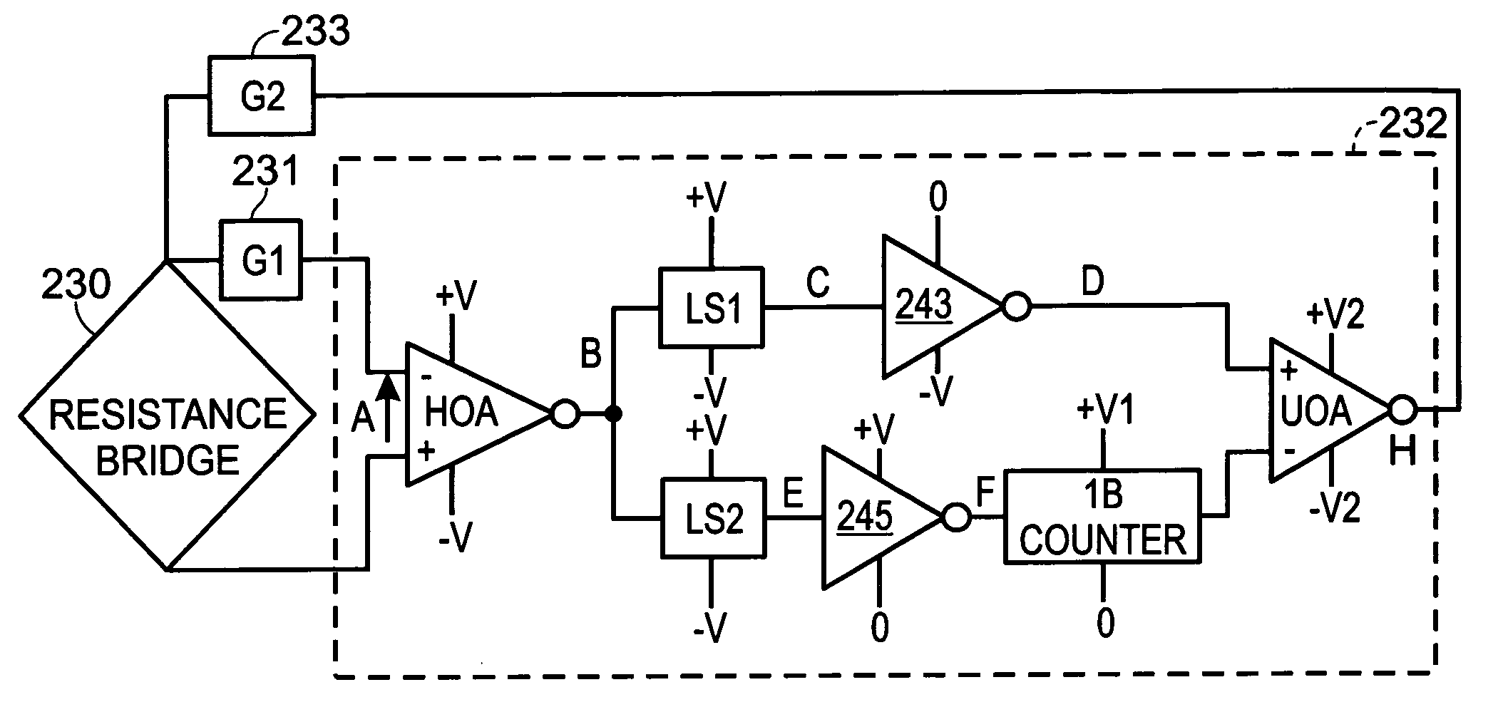
"The present invention is about a circuit that can adjust the resistance of a resistor to match a reference resistor in both increasing and decreasing directions. This is done using programmable resistance materials that can be reversibly increased or decreased by an applied electrical signal of the same polarity. The circuit includes a resistor bridge network and a pulse feedback circuit that generates a mono-polarity electrical pulse signal to adjust the resistance of the matching resistor. The circuit can be used in resistive memory devices such as phase change materials or perovskite materials. The feedback circuit can control the pulse amplitude, duration, and number of pulses to improve the resistance overshoot. The circuit can also include transmission gates to isolate signals and provide appropriate amplitude and duration for the mono-polarity electrical pulse signal output."

Problems solved by technology

Two important issues in the fabrication of resistors in microelectronic processing are the accuracy of the individual resistor and the accuracy of the ratio of a pair of resistors.
But for some circuits, this degree of precision is still not adequate.
For example, the resistance variations of merely 0.025 percent may compromise the linearity and accuracy of a 12-bit analog-to-digital converter.
In these prior art resistor trimming methods, the trimming action can be extremely difficult to reverse.

Method used


Image

  • Mono-polarity switchable PCMO resistor trimmer
  • Mono-polarity switchable PCMO resistor trimmer
  • Mono-polarity switchable PCMO resistor trimmer

Examples


Embodiment Construction

[0026]The present invention discloses a novel circuit to reversibly trim the resistor to match a reference resistor in electronics circuits by the use of programmable resistance material.

[0027]In the prior art resistance trimmer circuit, the act of resistor trimming often cannot be reversed due to the irreversibility of the resistance material or the trimming process. The prior art resistance material or the trimming process usually only allows the resistance to either increase or decrease, but not both.

[0028]For example, by laser trimming, the resistance can only increase due to the shaving or the shaping of the resistive material. Therefore the resistor material is designed with a very low initial resistance value, and is then trimmed to the appropriate resistance. If the resistor is trimmed excessively, the circuit cannot be repaired because the resistor cannot be reversed to the previous lower value. Similarly, the resistor trimming process is irreversible in fuse blowing or in ...


PUM


Abstract

Using programmable resistance material for a matching resistor, a resistor trimming circuit is designed to reversibly trim a matching resistor to match a reference resistor. The programmable resistance materials such as metal-amorphous silicon metal materials, phase change materials or perovskite materials are typically used in resistive memory devices and have the ability to change the resistance reversibly and repeatable with applied electrical pulses. The present invention reversible resistor trimming circuit comprises a resistance bridge network of a matching resistor and a reference resistor to provide inputs to a comparator circuit which generates a comparing signal indicative of the resistance difference. This comparing signal can be used to control a feedback circuit to provide appropriate electrical pulses to the matching resistor to modify the resistance of the matching resistor to match that of the reference resistor.

Description

FIELD OF THE INVENTION[0001]This invention relates in general to a circuit for resistor trimming, and more particularly, to a circuit for reversible precision adjustment or matching of thin film programmable resistors.BACKGROUND OF THE INVENTION[0002]Resistors play an important role in microelectronic circuits. A resistor is an electrical component designed to have an electrical resistance independent of the applied current or voltage. Two important issues in the fabrication of resistors in microelectronic processing are the accuracy of the individual resistor and the accuracy of the ratio of a pair of resistors.[0003]Many microeletronic circuits, such as precision analog amplifiers, require individual resistors to have a specific value to achieve the desired circuit performance level. Other circuits, such as differential amplifiers and analog-to-digital converters (ADC) or digital-to-analog converters (DAC), require accurate matching of two resistors, but not a specific value of in...

Claims


Application Information

Patent Timeline
Patent Type & Authority Patents(United States)
IPC IPC(8): H03L5/00
CPCH01L27/0802G11C13/0007G11C13/0004G11C2213/31
Inventor HSU, SHENG TENG
Owner XENOGENIC DEV LLC
Learn More