Optical amplifier

a technology of optical amplifiers and amplifiers, applied in the direction of electromagnetic transmission, optical transmission with multiple stages, transmission, etc., can solve the problems of large gain fluctuations, deterioration in the quality of transmission characteristics such as transmission distance and transmission band of wdm, and deterioration in transmission quality, so as to improve the efficiency of amplification and ensure constant gain in each of the optical amplification sections

Inactive Publication Date: 2006-08-01
FUJITSU LTD
View PDF5 Cites 10 Cited by
  • Summary
  • Abstract
  • Description
  • Claims
  • Application Information

AI Technical Summary

Benefits of technology

[0025]In an optical amplifier having the construction described above, by inserting the light blocking device at a predetermined position on the amplification medium in each of the plurality of amplification sections, the amount of pumping light which is wasted in amplification of the ASE light generated within the amplification medium and traveling in the opposite direction is reduced, and amplification efficiency is improved. As a result, the need to control the pumping light power of each optical amplification section in a complicated manner following a non-linear relationship, in order to ensure that the gain in each of the plurality of optical amplifications sections is constant can be eliminated. Therefore, the gain in each of the optical amplifications sections can be made constant using a simple method of controlling the pumping light power of each optical amplification section at a constant slope with respect to the number of wavelengths, that is, following a linear relationship. By realizing such constant gain control, the aforementioned transitional fluctuations in the residual channel power which occurred during changes in the number of wavelengths in the WDM light no longer occur, and it becomes possible to perform constant gain control of the optical amplification sections in a reliable manner.
[0026]According to the optical amplifier of the present invention as described above, even if the number of wavelengths in the input WDM light varies rapidly over a wide range, it is possible to realize flat gain wavelength characteristics regardless of the number of wavelengths, and a WDM light where the output power of the signal light of each wavelength is made at a constant level can be easily obtained.

Problems solved by technology

When this variation in the level of optical input to the optical repeater results in the total gain of the multistage EDFs deviating from a constant value, a problem occurs in that the flatness of the gain wavelength characteristics is no longer maintained, which causes tilt, and results in deterioration in the quality of such characteristics as the transmission distance and transmission band of the WDM optical transmission system.
The occurrence of such gain tilt causes the transmission quality to deteriorate.
But with such a control system, a problem occurs in that limitations imposed by the speed limit of the control circuit cause large fluctuations in gain whenever the number of wavelengths in the WDM light is increased or decreased.
Regarding the fluctuations which occur in the ASE optical power when the number of wavelengths changes, these remains unstable momentarily due to the response speed of the EDF.
In addition, while the ASE light of the ASE light within this C-band, which is traveling in the opposite direction to the signal light propagates towards the signal entry end, then as shown in FIG. 19 (C) the pumping light is wasted in amplification of this ASE light traveling in the opposite direction, which results in deterioration of the amplification efficiency.
Accordingly, there is a problem in that the complicated control of the pumping light power in an L band EDFA as shown in FIG. 18 leads to a reduction in the control speed of the electric circuit and an increase in the cost of the electric circuit.

Method used


Image

  • Optical amplifier
  • Optical amplifier
  • Optical amplifier

Examples


Embodiment Construction

[0047]A best mode for carrying out the invention is described below with reference to the appended drawings. Throughout all of the diagrams, the same reference numerals refer to the same or corresponding parts.

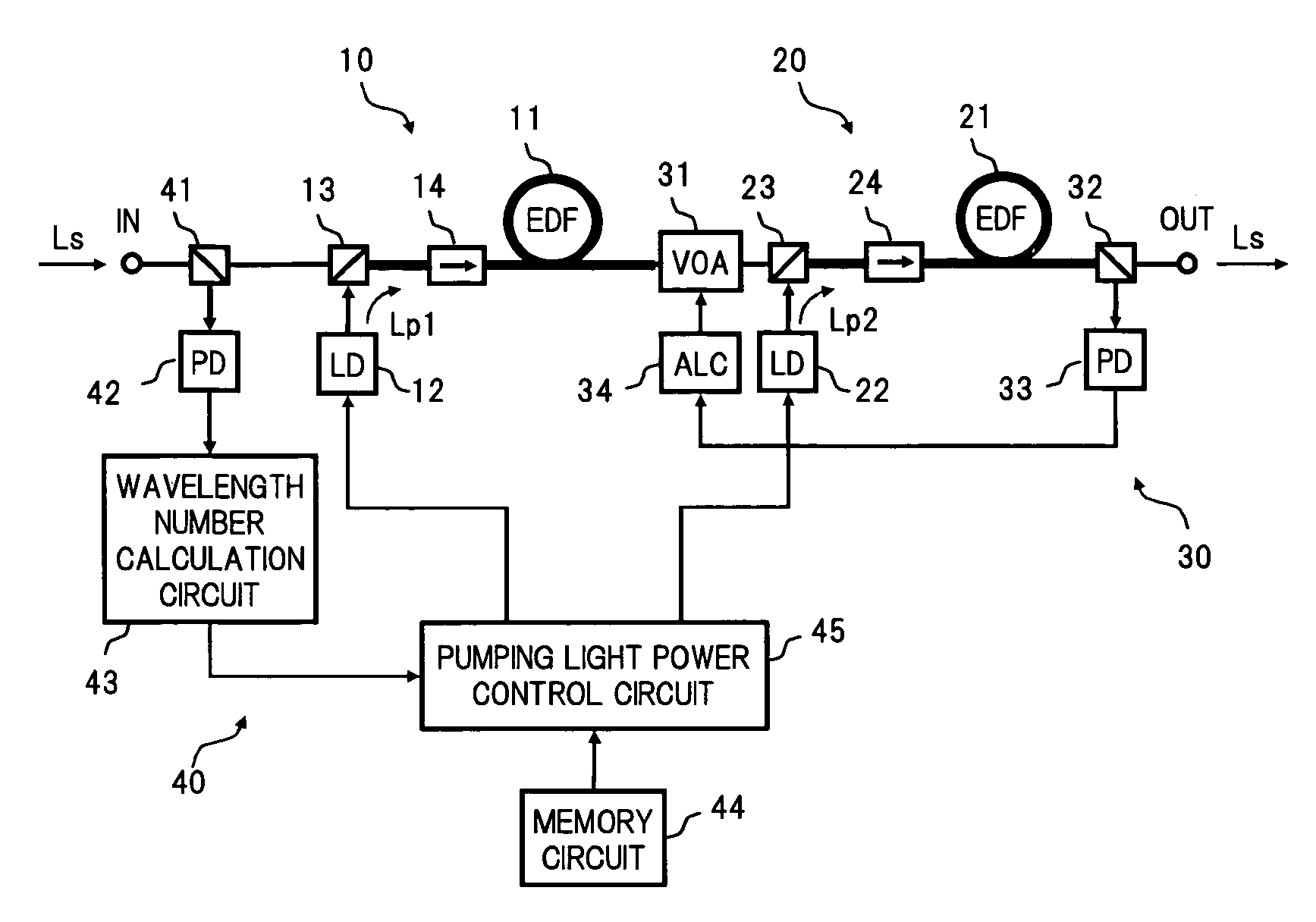
[0048]FIG. 1 is a block diagram showing the construction of a first embodiment of an optical amplifier according to the present invention.

[0049]In FIG. 1, the optical amplifier of the present embodiment comprises, for example, a first optical amplification section 10 and a second optical amplification section 20 connected in a cascade manner between an input terminal IN and an output terminal OUT, a constant output control section 30 which controls the power of WDM light Ls output to the output terminal OUT so as to keep the power constant, and a constant gain control section 40 which calculates the number of wavelengths based on the power of the WDM light Ls input to the input terminal IN, and in accordance with the number of wavelengths controls the power of each pumping lig...


PUM


Abstract

An optical amplifier of the invention comprises first and second optical amplification sections connected in a cascade manner between an input terminal and an output terminal. Optical isolators which block C-band ASE travelling in an opposite direction to L-band signal light, are inserted on the amplification medium of each of the optical amplification sections. A constant gain control section calculates the number of wavelengths based on the input power of signal light, and controls the pumping light power of each optical amplification section at a constant slope with respect to the number of wavelengths, so that the respective gains in the optical amplification sections corresponding to the number of wavelengths each become constant. As a result, it is possible to maintain flat gain wavelength characteristics even when receiving input of WDM light where the number of wavelengths varies rapidly over a wide range.

Description

BACKGROUND OF THE INVENTION[0001](1) Field of the Invention[0002]The present invention relates to an optical amplifier used in the field of optical communication, and in particular to an optical amplifier which amplifies wavelength division multiplexed (WDM) light which includes a plurality of optical signals arranged within a predetermined wavelength band.[0003](2) Description of the Related Art[0004]Recently, progress in Internet technology has led to a rapid increase in the demand for information services, and in trunk optical transmission systems, further increases in capacity are required, and a flexible network structure is desired. The most effective transmission technology for meeting such demands on optical transmission systems is WDM transmission. WDM transmission is a method of transmitting a plurality of optical signals with different wavelengths over a single fiber optic cable by multiplexing the signals. At present, progress is being made in the commercialization of WD...

Claims


Application Information

Patent Timeline
Patent Type & Authority Patents(United States)
IPC IPC(8): H04B10/12H01S3/06H01S3/067H01S3/094H01S3/0941H01S3/10
CPCH01S3/06758H04B10/296H01S3/0064H01S3/0078H01S3/06766H01S3/0677H01S3/0941H04B2210/003H01S3/1301H01S3/1305H01S3/1608H01S2301/02H01S2301/04H01S3/10069H01S3/10015H01S3/1001
Inventor TAKEYAMA, TOMOAKIINAGAKI, SHINYASASAKI, KEIKO
Owner FUJITSU LTD
Why Eureka
Try Eureka