Pre-stressed modular retaining wall system and method

Inactive Publication Date: 2006-08-08
CGL SYST
View PDF57 Cites 22 Cited by
  • Summary
  • Abstract
  • Description
  • Claims
  • Application Information

AI Technical Summary

Benefits of technology

[0028]An advantage of the present system is that structural pre-stressing may be sequentially modified, most typically increased, as the soil loading on the retaining wall changes.
[0029]Another advantage of the present system is that retaining wall (vertical) sections may be given sufficient and/or final pre-stress so as to allow for the construction of other structural members. If necessary, this could all take place before the soil loads are placed on the wall.
[0030]A further advantage of the present system is that the retaining wall structure may be stressed so as to always possess “residual”, or “net”, compressive stress on the “tension” side of any given header stack cross-section. This latter characteristic would be called on in environmentally hostile situations. For example, environmentally hostile situations may exist where naturally aggressive minerals are present in the ground water in contact with, or in close proximity to, the retaining wall, or where the retaining wall is a sea wall.
[0031]An advantage of the system of the present invention is ready availability. Short period cyclic casting of standard

Problems solved by technology

However, because of the ever increasing demands that are being placed on our city and urban environments and, most noticeably, on the country's transportation infrastructure, together with the need to preserve our natural environment while providing for the associated societal expectations, there is an increasing number of problematic sites where the currently available retaining wall options cannot provide an optimal solution.
In particular, for those sites that require “foundation-up” construction, there is a dearth of rapid construct, high capacity retaining wall systems possessing significant functional flexibility and which demand only a small construction footprin

Method used


Image

  • Pre-stressed modular retaining wall system and method
  • Pre-stressed modular retaining wall system and method
  • Pre-stressed modular retaining wall system and method

Examples


Embodiment Construction

[0122]Reference will now be made in detail to the present preferred embodiments of the invention, examples of which are illustrated in the accompanying drawings. The exemplary embodiments of this invention are shown in some detail, although it will be apparent to those skilled in the relevant art that some features may not be shown for the sake of clarity.

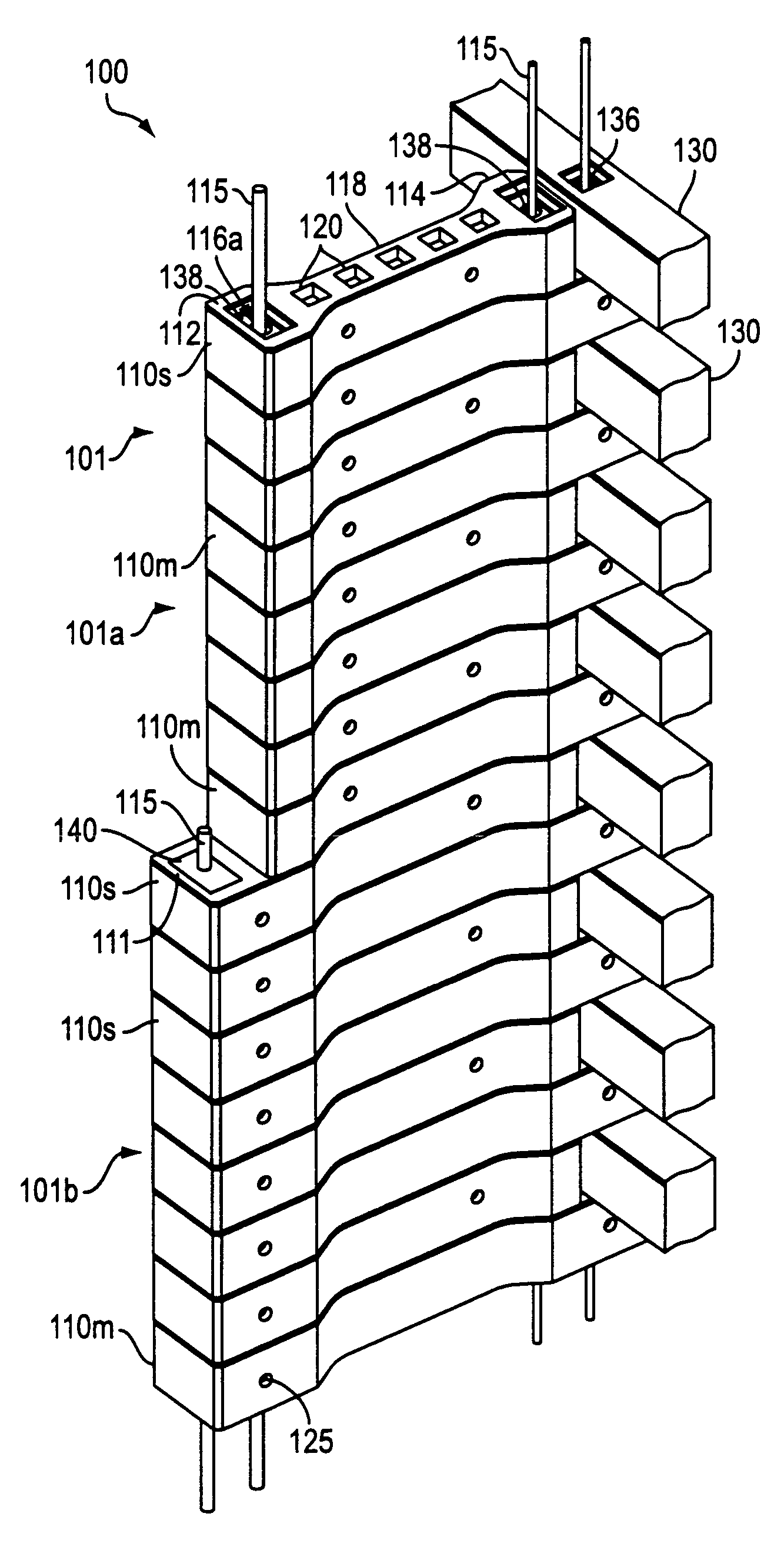
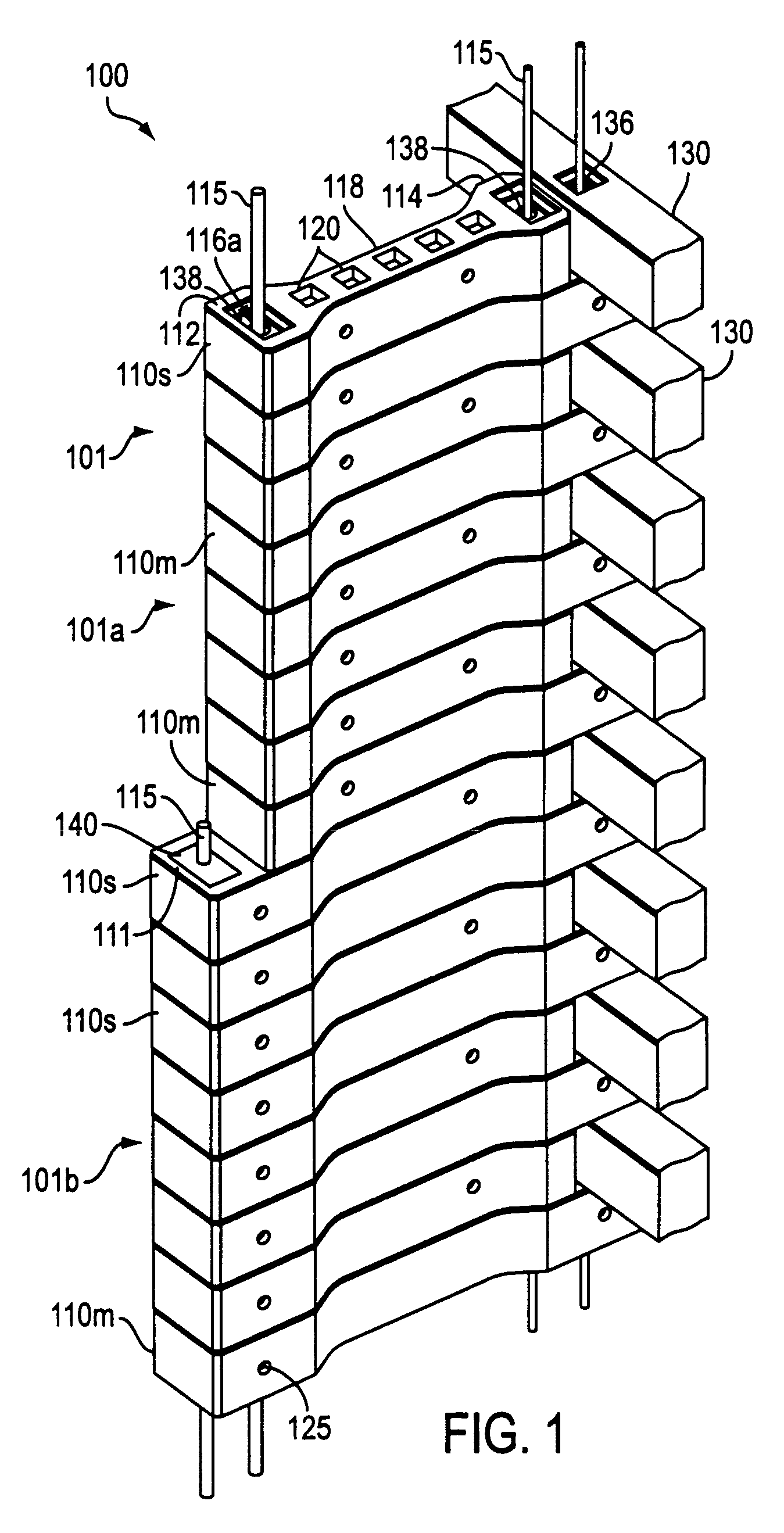
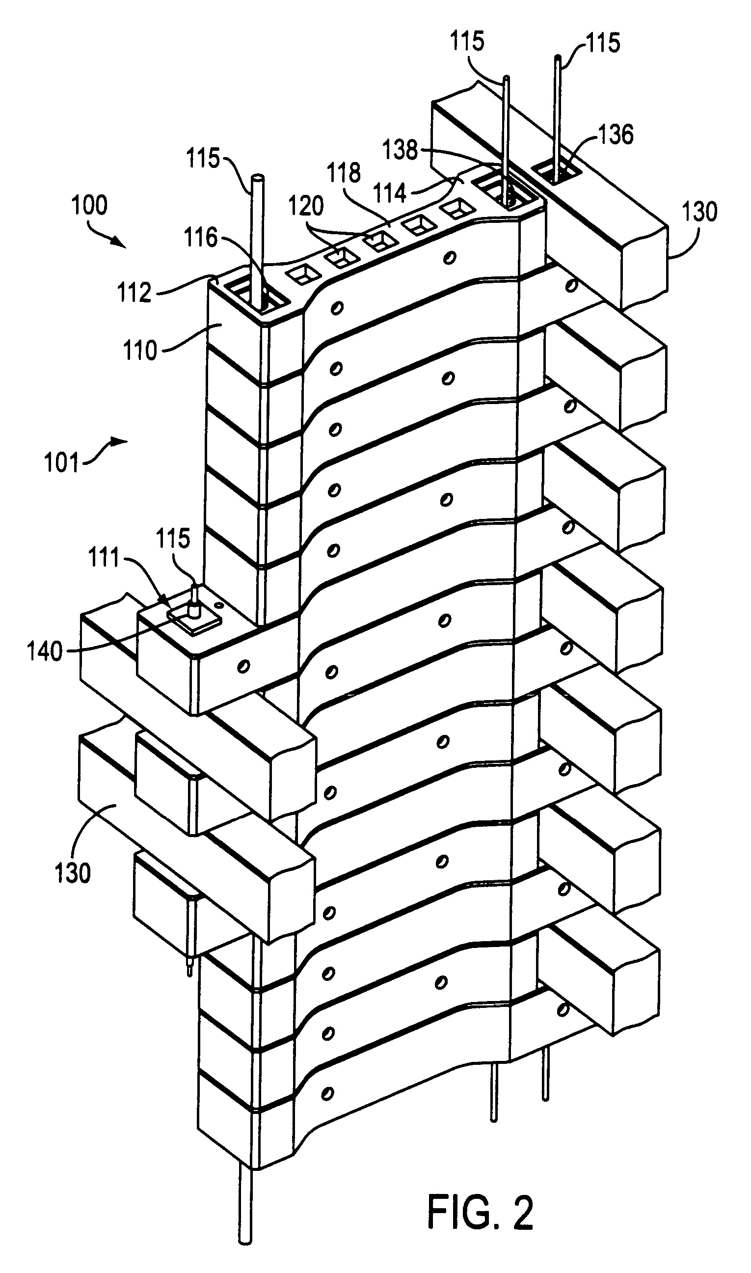
[0123]The systems of the present invention possess fundamental characteristics that are common to all of the constituent groups (i.e. subsystems). The systems are preferably comprised, at least partially, of pre-cast concrete components, called headers 110 or header units 110. These components, when stacked one on top of the other, form header stacks 101. These header stacks 101 are then augmented in a variety of ways. The augmenting members generally form secondary structural members 130. These components are secondary in the sense that they are available to resist soil loading, directly transferring these loads to the primary str...


PUM


Abstract

The present invention relates to a system and method for constructing a pre-stressed modular construction for supporting or retaining an applied load. In particular, the present invention relates to a system and method for pre-stressed modular retaining walls. The system comprises a plurality of header stacks constructed from a variety of header units. The header stacks are coupled by structural members. Active reinforcement elements are used to induce a pre-stressing force into the header stacks to support or retain the applied load. A method for constructing the modular construction is provided.

Description

CROSS-REFERENCE TO RELATED APPLICATIONS[0001]This application is a continuation of application Ser. No. 10 / 082,353, filed Feb. 26, 2002, abandoned, which is a continuation of application Ser. No. 09 / 474,069, filed Dec. 29, 1999, now U.S. Pat. No. 6,402,435.BACKGROUND OF THE INVENTION[0002]1. Field of the Invention[0003]The present invention relates to a system and method for fabricating a pre-stressed modular construction for supporting or retaining an applied load. More particularly, the present invention relates to a system and method for pre-stressed modular retaining walls.[0004]2. Related Art[0005]A retaining wall is an engineered structure that has the particular task of ensuring that a given unstable, or potentially unstable, soil mass is prevented from moving under the influence of gravity. Frequently, the retaining wall is also called upon to withstand a superimposed load, a surcharge load, on and / or within the soil mass, such as a highway, together with its traffic loading...

Claims


Application Information

Patent Timeline
IPC IPC(8): E02D29/02E02D17/18E01B1/00E02D17/20
CPCE02D29/0216E02D29/0283E02D29/0266E02D29/025
Inventor LEWIS, CYRRUS G.
Owner CGL SYST
Why Eureka
Try Eureka