Tube-type vortex reducer with retaining ring

a technology of retaining ring and reducer, which is applied in the direction of machines/engines, mechanical equipment, liquid fuel engines, etc., can solve the problems of high manufacturing cost, insufficient working space, and damage to compressor disks, so as to prevent the damage of compressor disks, reduce manufacturing costs, and reduce the cross-section of secondary air chambers

Inactive Publication Date: 2006-08-08
ROLLS ROYCE DEUT LTD & CO KG
View PDF11 Cites 35 Cited by
  • Summary
  • Abstract
  • Description
  • Claims
  • Application Information

AI Technical Summary

Benefits of technology

[0007]As a first advantage, the inventive design enables the secondary air tubes to be attached by way of the carrier ring. Their installation immediately on the compressor disks is, therefore, not required. This precludes the compressor disks from being damaged.
[0008]A further, major advantage lies in the fact that the cross-section of the secondary air chamber can be kept small since no tools or similar equipment for the installation of the secondary air tubes need to be introduced into the secondary air chamber. Generally, this results in an increased stiffness of the compressor disks, which also provides for vibration reduction. The selected assembly method according to the present invention fully precludes disk damage, such as scratches, nicks or the like caused by the peening process, thus avoiding premature failure or rework.
[0009]It is particularly favorable if the secondary air tubes are attached to the carrier ring by way of a form fit. In a preferred form, this can be accomplished by means of a mounting shoe provided at the end section of the secondary air tubes which can be inserted into a slot of the carrier ring and secured by means of a locking element. This arrangement provides for a high degree of axial stability. It also facilitates assembly to a considerable extent.
[0010]In a preferred form, the carrier ring according to the present invention is given the shape of an angle section. This increases the inherent stability of the carrier ring and also enables the carrier ring to be provided with bolt holes for attaching the carrier ring to one of the compressor disks by means of axial bolts. The different positions of the slots and the bolt holes provide for an assembly-friendly, space-saving design, with each of the bolt holes being located centrally between adjacent slots. To facilitate assembly, the carrier ring, in accordance with the present invention, can be split into several, for example three, segments. The carrier can be inserted into the disk interspace without straining the segments.
[0011]For safe retention of the radial inward end section of the secondary air tube, it is particularly favorable to locate it on the compressor disk by means of a form fit. To accomplish this, no separate tooling is required which, again, would require appropriate working space or could lead to damage.

Problems solved by technology

These designs are disadvantageous in that adequate working space must be provided to enable the secondary air tubes to be installed with suitable tools.
This involves high manufacturing costs.
Furthermore, the compressor disk may be damaged during the installation of the secondary air tubes.
Since this disk is very expensive, risk of damage is a cost-relevant aspect of considerable importance.

Method used


Image

  • Tube-type vortex reducer with retaining ring
  • Tube-type vortex reducer with retaining ring
  • Tube-type vortex reducer with retaining ring

Examples


Embodiment Construction

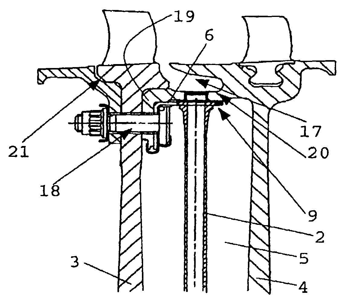
[0030]FIG. 17 shows a partial sectional view of an inventive gas turbine. Reference numeral 1 shows a compressor comprising rotor blades 11 and stator vanes 12. The rotor blades 11 are fixed to the compressor disks 3 or 4, respectively. These form a disk interspace 5 in which several, radial secondary air tubes 2 are arranged. Reference numeral 13 indicates a combustion chamber, while reference numeral 14 designates a turbine in schematic representation. The arrows schematically indicate the route of the secondary air flow.

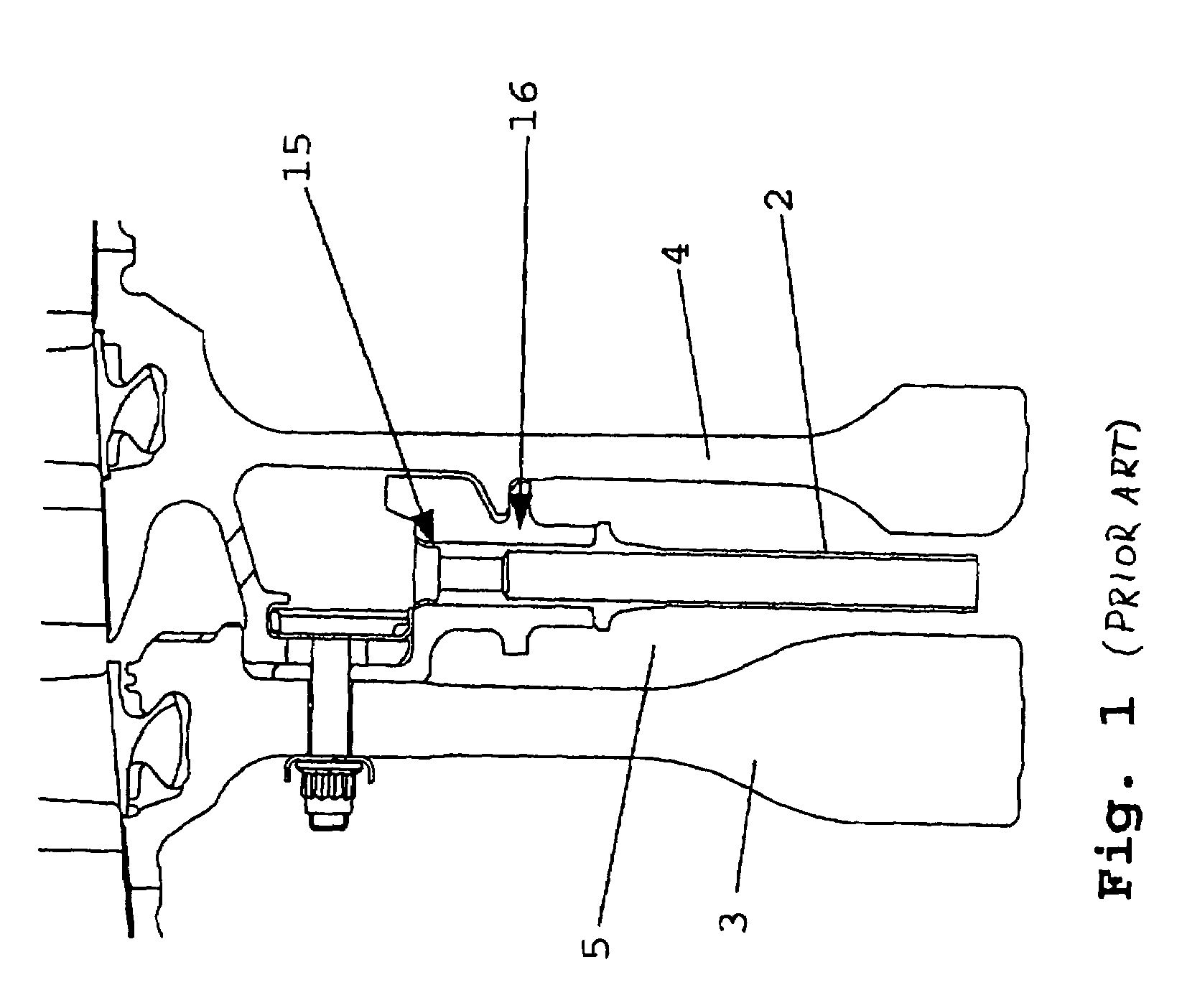
[0031]FIGS. 1 and 2 show embodiments according to the state of the art. Obviously, the end sections of the secondary air tubes are riveted, as indicated by the reference numeral 15. Reference numeral 16 designates an additional carrier disk which represents an additional volume element and is fitted in the disk interspace 5.

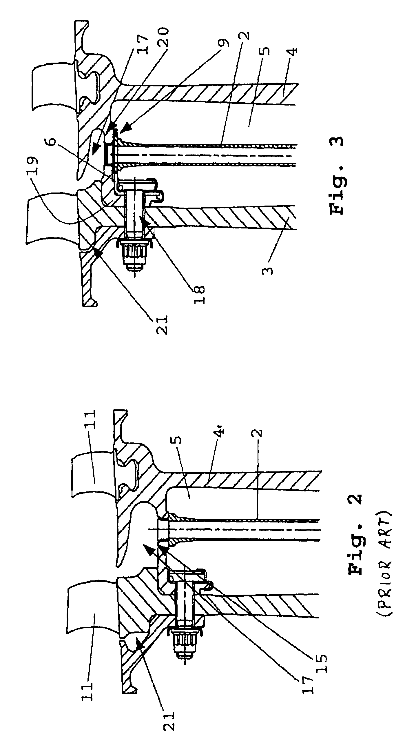
[0032]FIG. 2 shows a similar embodiment, with a riveted joint again being indicated by the reference numeral 15. As becomes apparent, a very l...


PUM


Abstract

A tube-type vortex reducer conducts cooling air in a compressor (1) of a gas turbine. Radial secondary air tubes (2) are arranged in a disk interspace (5) and attached to a compressor disk (3) with their radial outward end sections. The end sections of the secondary air tubes (2) are attached to a separate carrier ring (6), which is connected to a compressor disk (3).

Description

[0001]This application claims priority to German Patent Application DE10310815.7 filed Mar. 12, 2003, the entirety of which is incorporated by reference herein.BACKGROUND OF THE INVENTION[0002]This invention relates to a tube-type vortex reducer. More particularly, the present invention relates to a vortex reducer for the conduction of cooling air in a compressor of a gas turbine, with radial secondary air tubes being arranged in a disk interspace and attached to a compressor disk with their radial outward end section.[0003]In the state of the art, designs are known in which the secondary air tubes are fitted to corresponding locations on the disks by a pressing, riveting, screwing, snapping or forging process. These designs are disadvantageous in that adequate working space must be provided to enable the secondary air tubes to be installed with suitable tools. Therefore, the secondary air chamber, through which the secondary air enters the secondary air tubes, must be given a relat...

Claims


Application Information

Patent Timeline
Patent Type & Authority Patents(United States)
IPC IPC(8): F01D25/12F01D5/08F02C7/18F04D29/32F04D29/64
CPCF01D5/082F04D29/644F04D29/321F02C7/18
Inventor FITZGERALD, IANSEYDEL, CHRISTIAN
Owner ROLLS ROYCE DEUT LTD & CO KG
Why Eureka
Try Eureka