Scanning microscope having an acoustooptical component

a scanning microscope and component technology, applied in the direction of instruments, beam/ray focussing/reflecting arrangements, electric discharge lamps, etc., can solve the problems of negative repercussions, complex retrospective calculation of laser power level fluctuations upon image calculation, and subject to the light power level of the illuminating ligh

Active Publication Date: 2006-08-08
LEICA MICROSYSTEMS CMS GMBH
View PDF6 Cites 1 Cited by
  • Summary
  • Abstract
  • Description
  • Claims
  • Application Information

AI Technical Summary

Benefits of technology

[0012]It is therefore an object of the present invention to provide a scanning microscope in which the light power level of the sample illuminating light is, in eff

Problems solved by technology

The light power level of the illuminating light is subject, to fluctuations over time as a result of various effects, with negative repercussions in the context of sample examination.
For example, calculating out the laser power level fluctuations retrospectively upon image calculation is complex, and is not always an entirely satisfactory correction method.
In addition, the calculated scan image will wash out at locations with very low detected light powe

Method used


Image

  • Scanning microscope having an acoustooptical component
  • Scanning microscope having an acoustooptical component
  • Scanning microscope having an acoustooptical component

Examples


Embodiment Construction

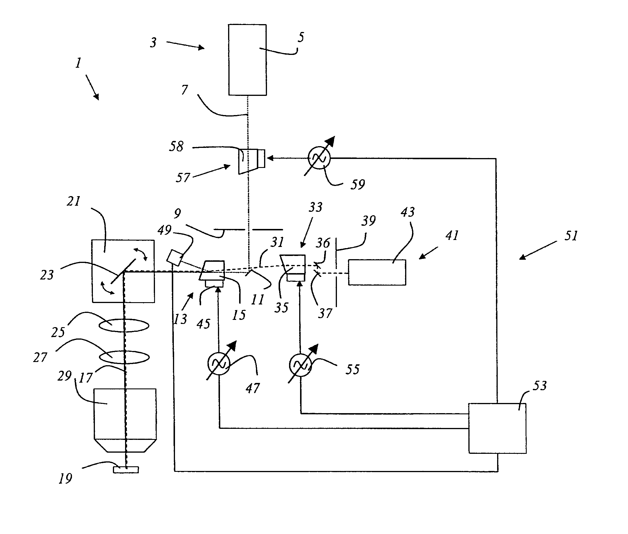
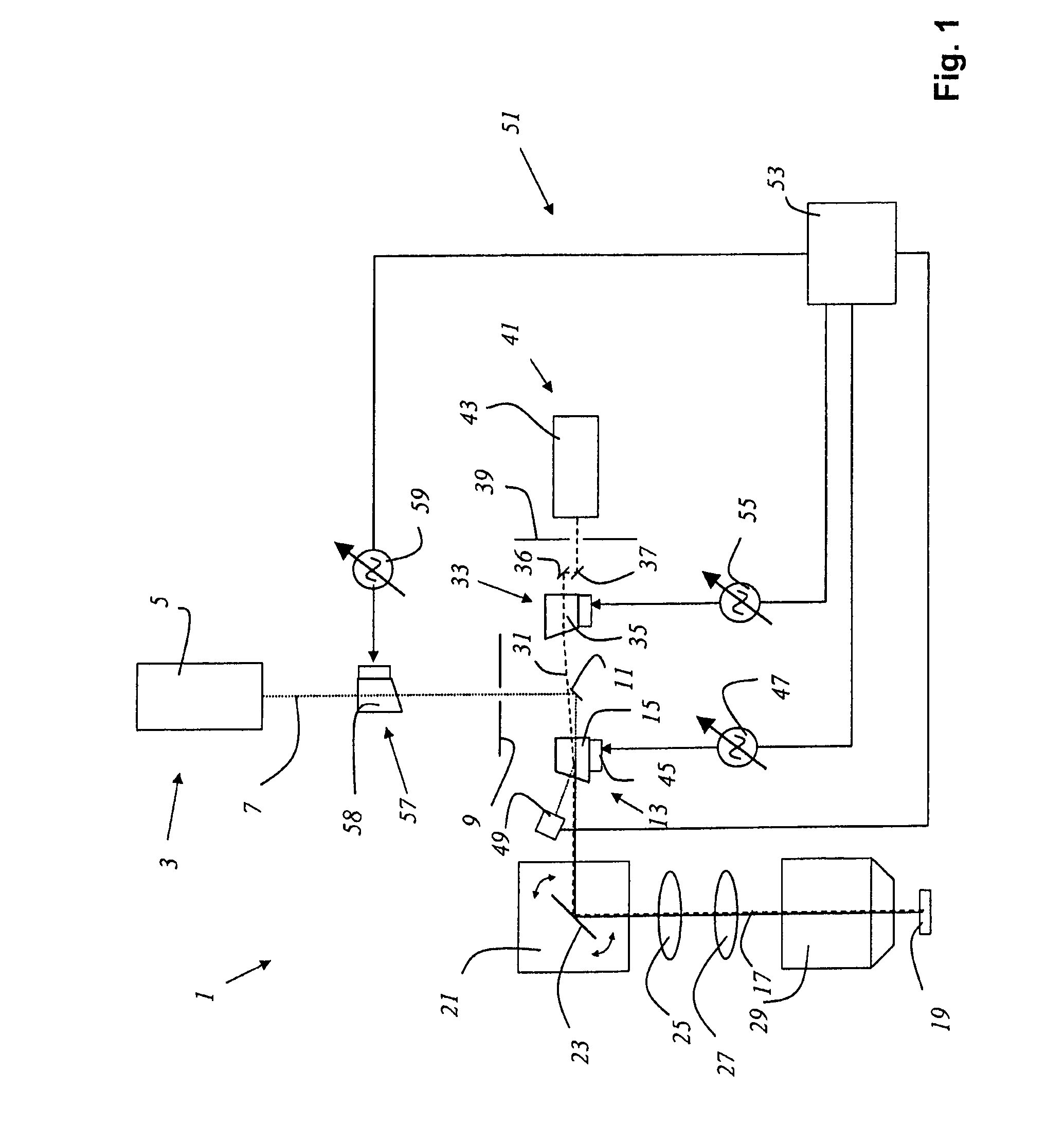
[0024]FIG. 1 shows a scanning microscope 1 according to the present invention which is embodied as a confocal scanning microscope. A light source 3, which is embodied as a multiple-line laser 5, emits output light shaped into an output light beam 7. This passes through illumination pinhole 9 and is directed by a deflection mirror 11 to an acoustooptical component 13 that is embodied as AOTF 15, which splits off from output light beam 7 an illuminating light beam 17 for illumination of a sample 19. From acoustooptical component 13, illuminating light beam 17 travels to a beam deflecting device 21, which contains a gimbal-mounted scanning mirror 23 and guides illuminating light beam 17 through scanning optical system 25, tube optical system 27, and objective 29, over or through sample 19. Detected light beam 31 coming from sample 19 passes in the opposite direction through objective 29, tube optical system 27, and scanning optical system 25, and travels via scanning mirror 23 to acous...


PUM


Abstract

A scanning microscope having an acoustooptical component that splits out illuminating light for illumination of a sample from the output light of at least one light source, and conveys detected light proceeding from the sample to a detector, comprises, in the beam path of the output light from which the illuminating light is split out, at least one monitoring detector which is the measuring element of a control circuit. The scanning microscope is characterized in that fluctuations over time in the illuminating light power level are largely eliminated.

Description

CROSS REFERENCE TO RELATED APPLICATIONS[0001]This application claims priority to German patent application 103 02 259.7, the subject matter of which is hereby incorporated by reference herein.FIELD OF THE INVENTION[0002]The invention concerns a scanning microscope having an acoustooptical component that splits out illuminating light for illumination of a sample from the output light of at least one light source, and conveys detected light proceeding from the sample to a detector.BACKGROUND OF THE INVENTION[0003]In scanning microscopy, a sample is illuminated with a light beam in order to observe the reflected or fluorescent light emitted from the sample. The focus of an illuminating light beam is moved in an object plane by means of a controllable beam deflection device, generally by tilting two mirrors, the deflection axes usually being perpendicular to one another so that one mirror deflects in the X direction and the other in the Y direction. Tilting of the mirrors is brought abo...

Claims


Application Information

Patent Timeline
IPC IPC(8): H01J3/14G02F1/33H01J40/14H01J5/16G02B21/00G02F1/11G02F1/13
CPCG02B21/0032G02B21/0052G02B21/0068G02B21/008G02F2203/07G02F1/113G02F1/13
Inventor KNEBEL, WERNERSTORZ, RAFAELMOELLMANN, KYRA
Owner LEICA MICROSYSTEMS CMS GMBH
Why Eureka
Try Eureka