Drive method of an electro optical device, a drive circuit and an electro optical device and an electronic apparatus

a drive circuit and drive circuit technology, applied in the direction of static indicating devices, instruments, television systems, etc., can solve the problems of low relatively slow response time of liquid crystal in comparison with display devices, etc., and achieve the effect of superiority of sight recognition of moving images

Active Publication Date: 2006-08-08
BOE TECH GRP CO LTD
View PDF8 Cites 12 Cited by
  • Summary
  • Abstract
  • Description
  • Claims
  • Application Information

AI Technical Summary

Benefits of technology

[0013]It is necessary to enhance the response characteristic of liquid crystal in order to enhance reproductiveness for a moving image when such image is displayed in a liquid crystal display as an electro optical device. However, the response time of liquid crystal is relatively slow in comparison with display device, such as plasma display. Hence, a problem exists that sight recognition for a moving image is low.
[0050]According to such a structure, superiority of sight recognition of a moving image can be attained and multi-levels of gray scale display can be provided simultaneously.

Problems solved by technology

However, the response time of liquid crystal is relatively slow in comparison with display device, such as plasma display.
Hence, a problem exists that sight recognition for a moving image is low.

Method used


Image

  • Drive method of an electro optical device, a drive circuit and an electro optical device and an electronic apparatus
  • Drive method of an electro optical device, a drive circuit and an electro optical device and an electronic apparatus
  • Drive method of an electro optical device, a drive circuit and an electro optical device and an electronic apparatus

Examples


Embodiment Construction

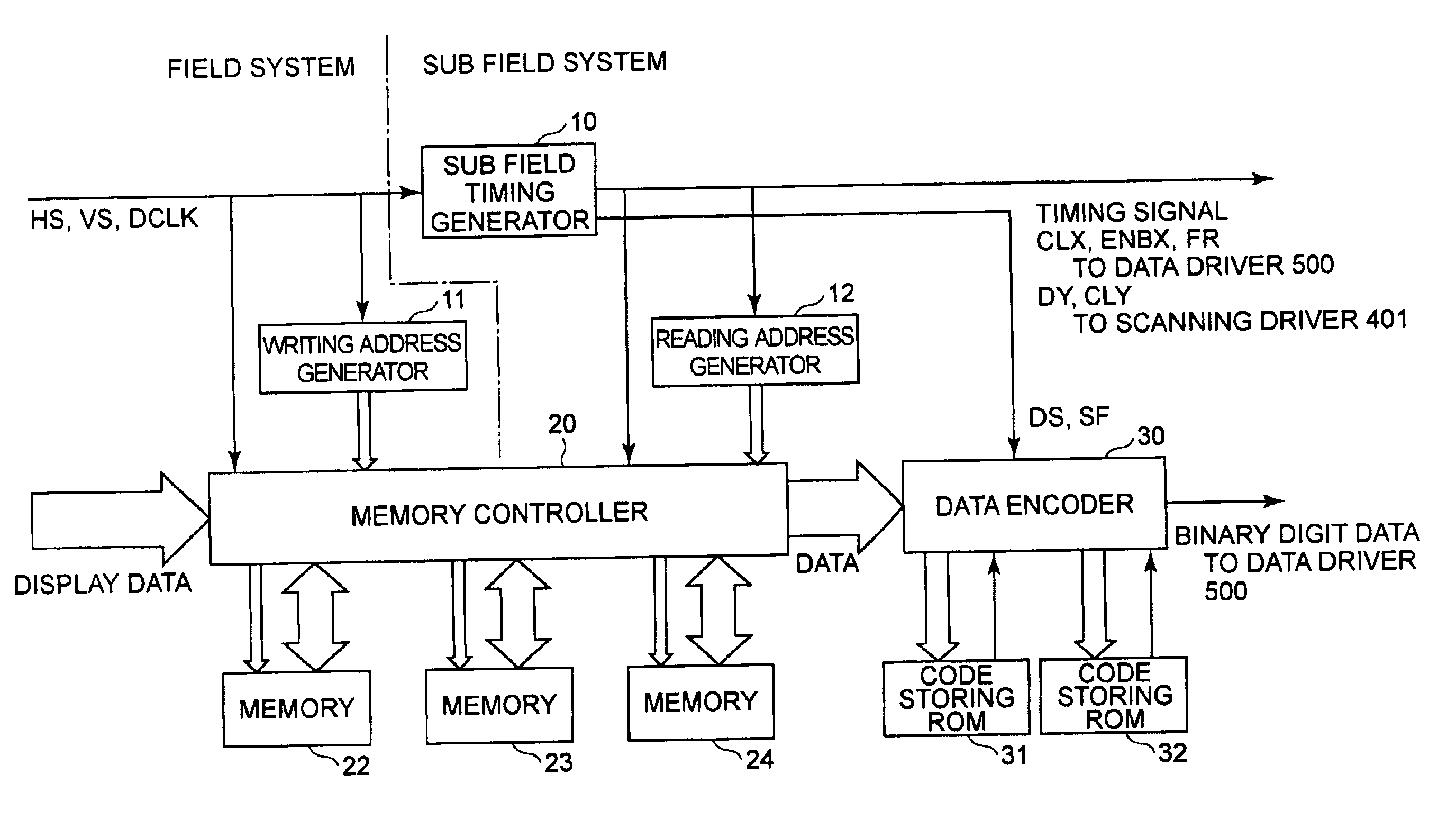
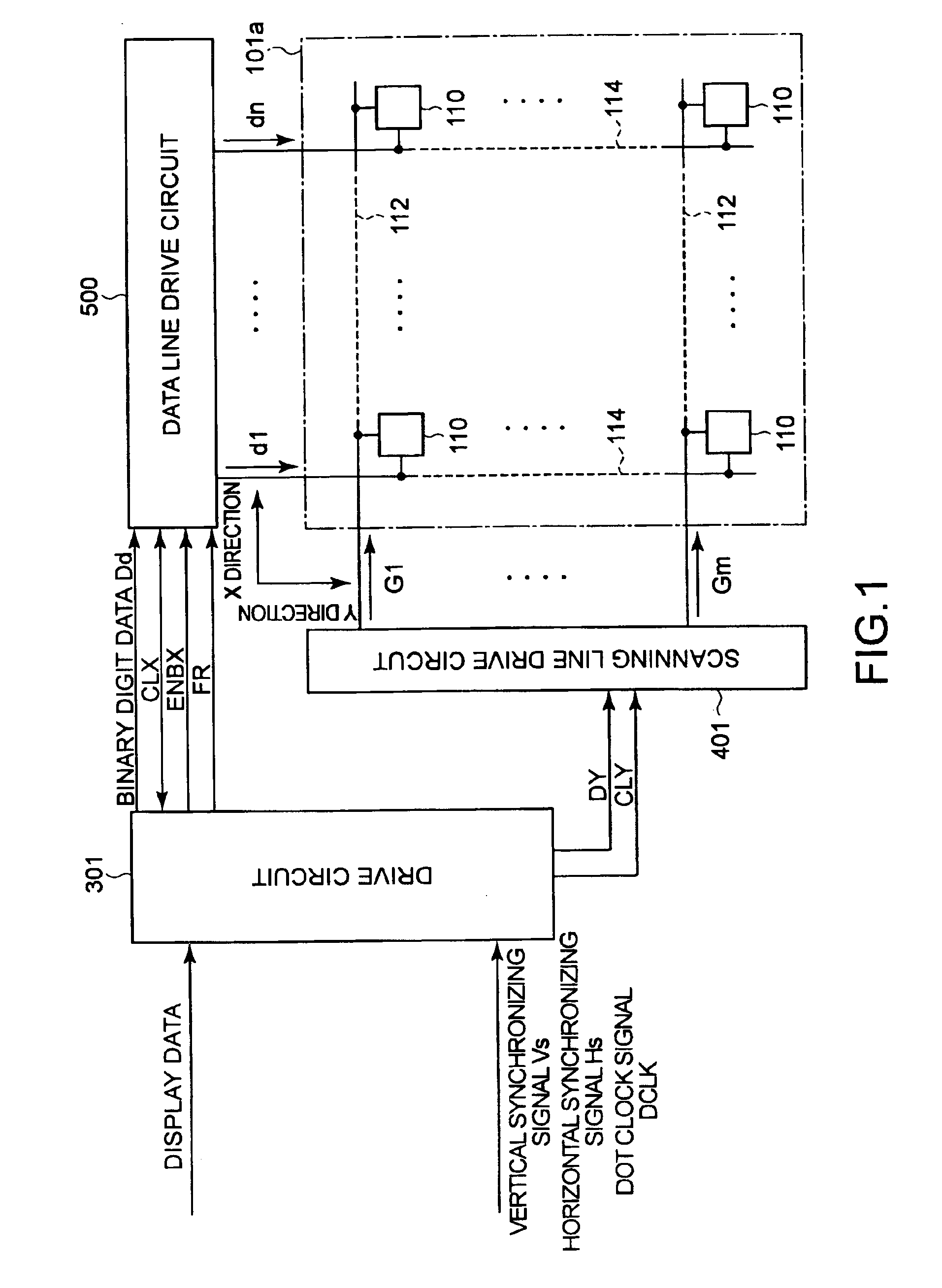
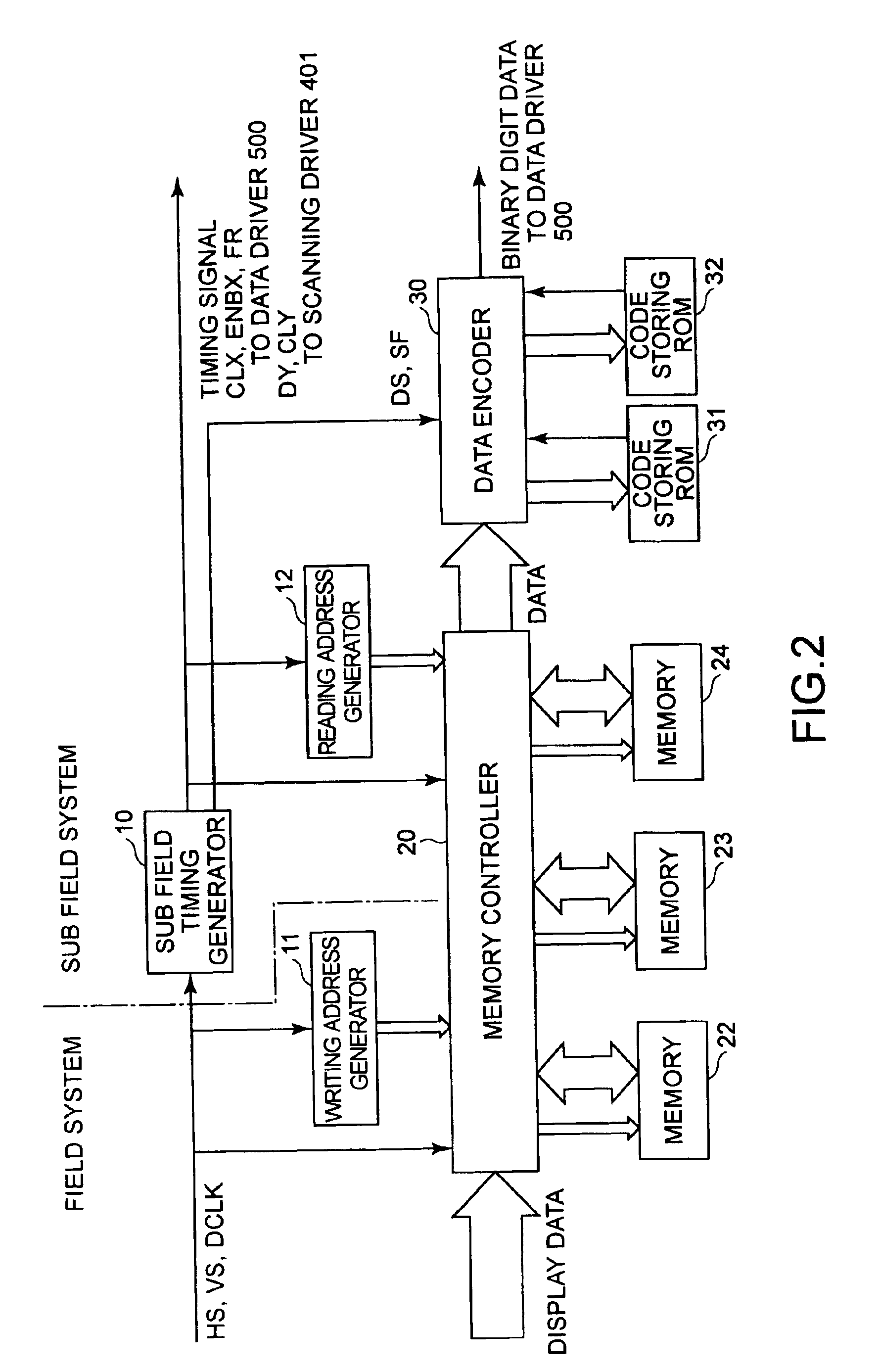
[0072]An exemplary embodiment of the present invention is hereinafter explained in detail with reference to drawings. FIG. 1 is a schematic showing an electro-optical device related to a first exemplary embodiment of the present invention.

[0073]An electro-optical device of the present exemplary embodiment is a liquid crystal device, in which liquid crystal is used as electro-optical material, for example. The device includes a structure where an element substrate and an opposite substrate are affixed together, keeping a specific spacing as described hereinafter, and liquid crystal as electro-optical material is sandwiched within this spacing. A display mode of the electro-optical device is normally black, namely a white image is displayed when voltage is applied to a pixel and a black image is displayed when voltage is not applied.

[0074]According to the present exemplary embodiment, a sub-field drive method is adopted as a method of driving liquid crystal, where one field is divided...


PUM

PropertyMeasurementUnit
transmittanceaaaaaaaaaa

Abstract

A method of sub-field drive can display with a mode of placing emphasis on responsiveness and display with a mode of placing emphasis on gray-scale reproductiveness.A field is divided into plural sub-fields on a time axis, and each of such sub-fields is a control unit of driving a pixel. A code storing ROM stores a code that controls sub-fields to collecting on-voltage intensively in a former part of a field based on display data. Another code storing ROM stores a code that controls sub-fields to increase levels of gray scale based on display data. A data encoder determines whether each pixel of display data is an edge part of a moving image or not, selects a code that enables superior display in responsiveness at the edge part of a moving and selects a code that enables superior display in gray scale reproductiveness in other parts from the ROMs. Therefore, superior sight recognition of a moving image can be attained and reproduction of multi-levels gray scale in a still image can be available simultaneously.

Description

BACKGROUND OF THE INVENTION[0001]1. Field of Invention[0002]The present invention relates to a method of driving an electro optical device where gray-scale display is controlled by a sub-field drive method, a drive circuit and an electronic apparatus thereof.[0003]2. Description of Related Art[0004]In the related art, an electro-optical device, such as a liquid crystal display using liquid crystal as electro-optical material, for example, can be unitized for a display portion of various kinds of information apparatus, liquid crystal TV, etc., as a display device that can replace a cathode ray tube (CRT).[0005]Such a liquid crystal display device, for example, includes pixel electrodes arranged in a matrix, an clement substrate including switching elements, such as TFT's (Thin Film Transistors), connected to these pixel electrodes, an opposite substrate including an electrode opposite to each of the pixel electrodes and liquid crystal as electro-optical material filled between these ...

Claims


Application Information

Patent Timeline
Patent Type & Authority Patents(United States)
IPC IPC(8): G09G3/36G02F1/13G02F1/133G09G3/20H04N5/66
CPCG09G3/3648G09G3/2025G09G2320/106G09G2320/0261G09G2310/027
Inventor IISAKA, HIDEHITO
Owner BOE TECH GRP CO LTD
Why Eureka
Try Eureka