Component mounting apparatus and component mounting method, and recognition apparatus for a component mount panel, component mounting apparatus for a liquid crystal panel, and component mounting method for a liquid crystal panel

Inactive Publication Date: 2006-08-08
PANASONIC CORP
View PDF47 Cites 7 Cited by
  • Summary
  • Abstract
  • Description
  • Claims
  • Application Information

AI Technical Summary

Benefits of technology

[0014]The present invention is devised to solve the aforementioned problem and has for its second object to provide a recognition apparatus for a component mount panel, a component mounting apparatus for a liquid crystal panel, and a component mounting method for a liquid crystal panel for being able to mount components to specified component mount positions even if panels are deflected.
[0018]According to the component mounting apparatus as above, each object is transferred while held from its lower side. Therefore, a suction force for this holding can be small as compared with a case where an object is held at its upper side, whereby suction irregularity due to action of the suction force is prevented. Since the transfer device is placed at the lower side of the object, there is no particular obstruction to removing the object from the apparatus. Even if the apparatus stops due to a failure or the like, work required for removing the object from the apparatus is facilitated and superior maintainability is realized.
[0022]Further, each of the transfer devices may have two transfer arms for supporting an object at both end parts thereof. According to the above component mounting apparatus, suction irregularity at a central part of the object can be perfectly prevented.
[0029]According to the above component mounting method, since each object is held at its lower side, a suction force for holding the object can be smaller, because of a weight of the object, than when the object is held at its upper side; thus preventing a suction irregularity by action of a suction force. Since transfer devices are set to the lower side of the objects, there is no hinderance when objects are to be removed from the apparatus. Removing objects from the apparatus is facilitated even if the apparatus stops by a failure or the like, and a superior maintainability is realized.
[0052]According to the recognition apparatus for a component mount panel in the third aspect of the present invention as described hereinabove, the control device controls the panel hold device to negate the deflection amount of the panel generated when held by the panel holding device, and to position the panel marks to the bonding height position when the panel is arranged at the image pickup device. Since the panel is in a state free from deflection when images of the panel marks are picked up, the images of the panel marks can be picked up with higher accuracy than is conventional.
[0053]According to the component mounting apparatus for a liquid crystal panel in accordance with the fourth aspect and the component mounting method for a liquid crystal panel in accordance with the fifth aspect of the present invention, there are arranged the image pickup device, the panel holding device, the component holding device, and the control device. The control device controls operation of the panel holding device so as to negate the deflection amount of the liquid crystal panel generated when held by the panel holding device, and to position the panel marks to the component bonding height position when the liquid crystal panel is arranged at the image pickup device, and moreover, the control device makes the component holding device mount components onto the liquid crystal panel at the bonding height position with the component marks positioned at the bonding height position. Accordingly, the images of the panel marks can be picked up in a state without any deflection of the liquid crystal panel. Moreover, a position where the images of the panel marks and the component marks are picked up are made equal to a position where the component is to be mounted to the liquid crystal panel. Thus, unnecessary operations for moving the panel holding device and the component holding device are reduced, so that accuracy for mounting components can be improved as compared with the prior art.

Problems solved by technology

However, the conventional electronic component mounting apparatus as above has problems as follows.
This increase of the hold force brings about an irregularity (shaded parts c) in suction by the suction pad at a periphery of the suction pad, and this suction irregularity leads to a display irregularity in highly fine and high-quality liquid crystal panels, thereby lowering an image quality.
However, the transfer arms 55 above the liquid crystal panels make it impossible to remove the liquid crystal panels even when the conventional electronic component mounting apparatus as above comes to a halt because of a failure or the like, or require complicated work even if it is possible.
The above-described conventional component mounting apparatus still includes problems as below.

Method used


Image

  • Component mounting apparatus and component mounting method, and recognition apparatus for a component mount panel, component mounting apparatus for a liquid crystal panel, and component mounting method for a liquid crystal panel
  • Component mounting apparatus and component mounting method, and recognition apparatus for a component mount panel, component mounting apparatus for a liquid crystal panel, and component mounting method for a liquid crystal panel
  • Component mounting apparatus and component mounting method, and recognition apparatus for a component mount panel, component mounting apparatus for a liquid crystal panel, and component mounting method for a liquid crystal panel

Examples


second embodiment

[0107]A recognition apparatus for a component mount panel, a component mounting apparatus for a liquid crystal panel and, a component mounting method for a liquid crystal panel in a second embodiment of the present invention will be described with reference to the drawings in which like parts are designated by like reference numerals.

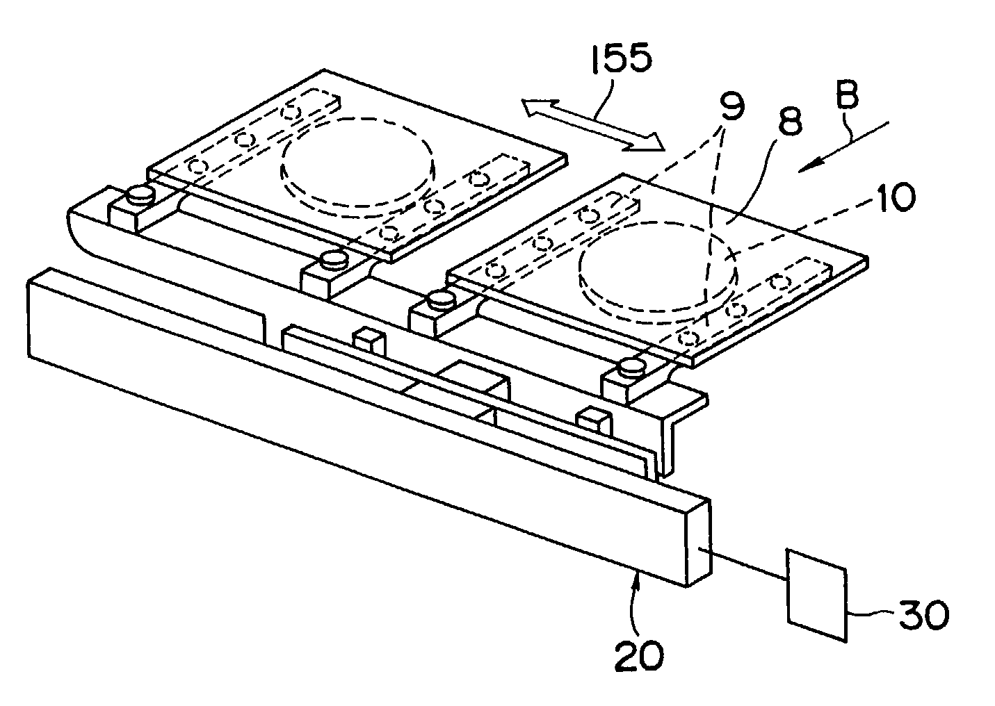
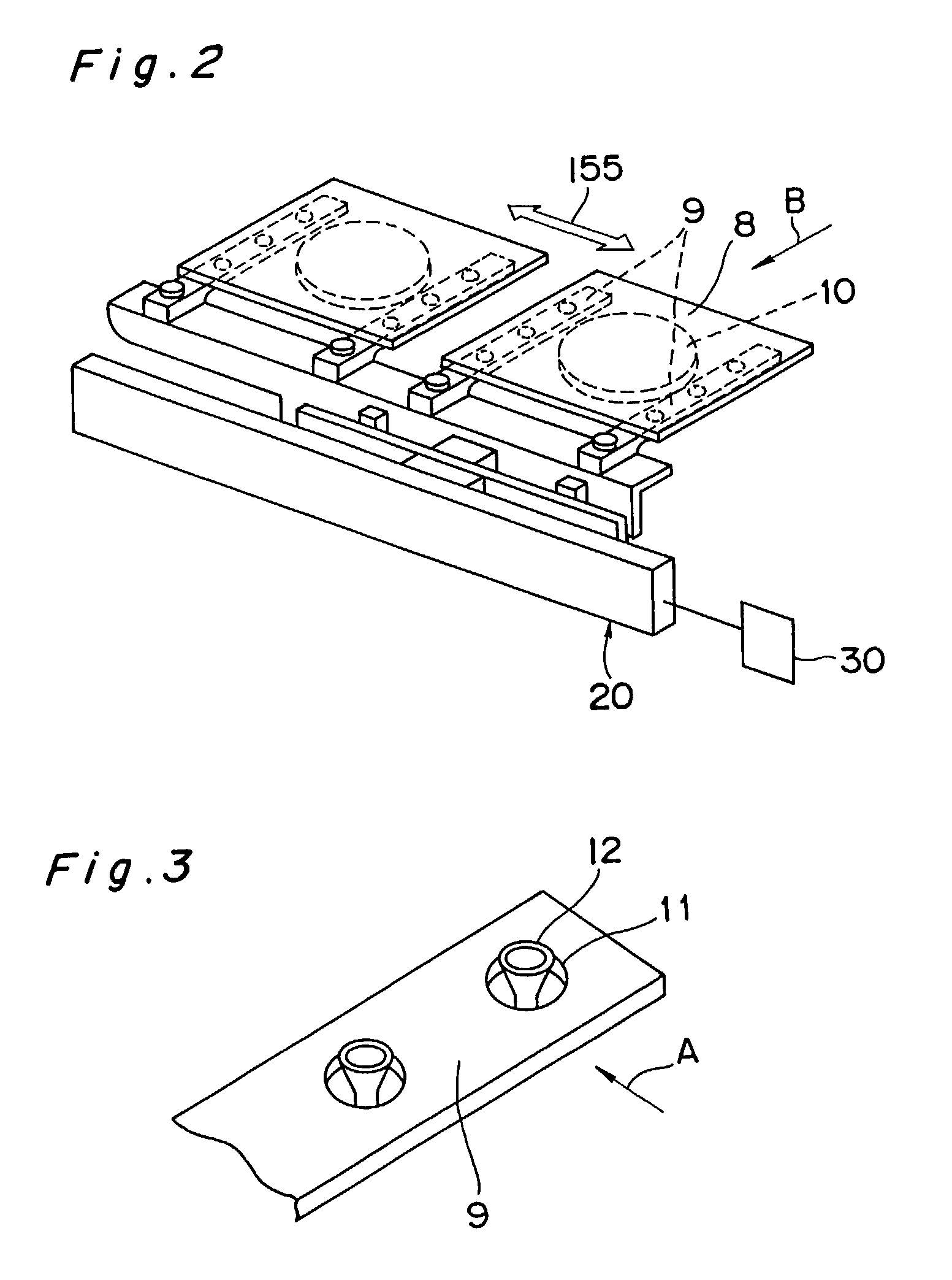
[0108]The present embodiment adopts, as a panel to which components are to be mounted, a panel for liquid crystal display which is formed of a glass substrate such as the one described with reference to FIG. 22. However the panel is not restricted to a liquid crystal panel. Moreover, an electronic component will be discussed as an example functioning as a component.

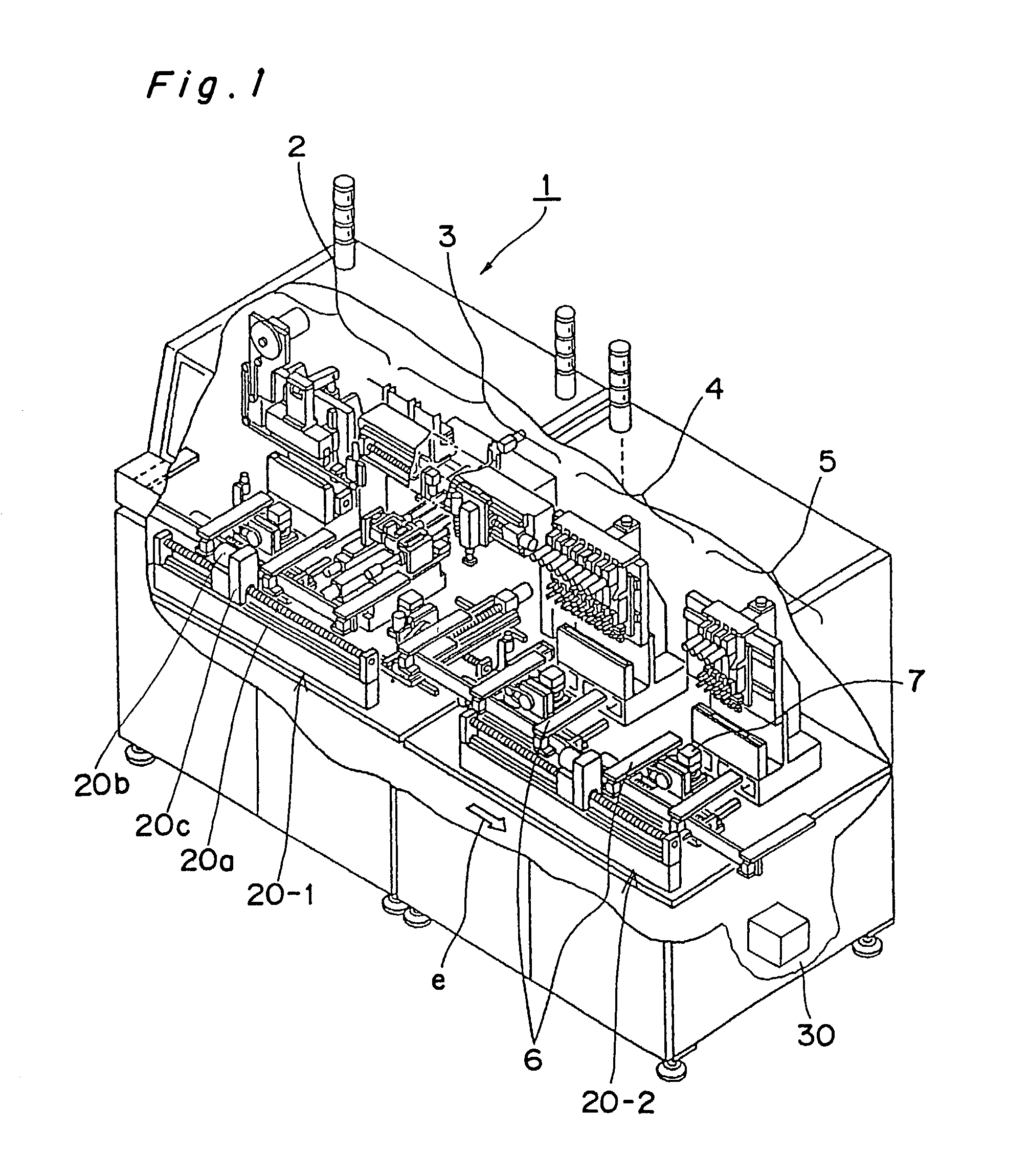
[0109]A component mounting apparatus 101 for a liquid crystal panel with a recognition apparatus for a component mount panel, i.e., with a recognition apparatus for a liquid crystal panel in this embodiment is shown in FIG. 15. The component mounting apparatus 101 shown in FIG. 15 corresponds...


PUM

PropertyMeasurementUnit
Forceaaaaaaaaaa
Areaaaaaaaaaaa

Abstract

Transfer of liquid crystal panels to subsequent processes is performed with the panels placed on transfer arms and held by suction pads. A small suction force can be sufficient, and a suction irregularity is prevented. The transfer arms are arranged at a lower side of the liquid crystal panels, thus not obstructing the liquid crystal panels. In arranging the liquid crystal panels at an image pickup device, a panel holding device is controlled to be driven so as to position panel marks to a bonding height position while negating a deflection amount of the liquid crystal panels, and furthermore a component holding device is controlled to be driven so as to position component marks to the bonding height position and to mount electronic components to the liquid crystal panels at the bonding height position.

Description

TECHNICAL FIELD[0001]The present invention relates to a component mounting apparatus and a component mounting method with a transfer mechanism for mounting a component onto a liquid crystal panel or the like. Further, the present invention relates to: a recognition apparatus for a component mount panel for picking up and then recognizing images of both a panel, e.g., liquid crystal panel or the like, and an electronic component to be mounted thereon; a component mounting apparatus for a liquid crystal panel including the recognition apparatus; and a component mounting method for a liquid crystal panel performed by the component mounting apparatus for the liquid crystal panel.BACKGROUND ART[0002]There have conventionally been known electronic component mounting apparatuses for mounting electronic components to objects while transferring, with use of arms, the objects to which the electronic components are to be mounted. There is, for example, an electronic component mounting apparatu...

Claims


Application Information

Patent Timeline
IPC IPC(8): G06F19/00G02F1/13G02F1/1333H01L21/683H05K13/00H05K13/08
CPCH01L21/687H01L21/68707H05K13/0061H05K13/08H01L21/6838G02F1/1333G02F1/13452G05B2219/37555G05B2219/37563G05B2219/37572G05B2219/45051Y10T29/53191Y10T29/53G02F1/13
Inventor TSUJI, SHINJIRONISHIMOTO, TOMOTAKAMURATA, TAKAHIKOIDA, MASAYUKI
Owner PANASONIC CORP
Why Eureka
Try Eureka