Eureka AIR delivers breakthrough ideas for toughest innovation challenges, trusted by R&D personnel around the world.

Optical receptacle with low transmission loss and photoelectric conversion module for the same

a technology of optical receptacles and conversion modules, which is applied in the field of optical receptacles with low transmission loss and photoelectric conversion modules for the same, can solve the problems of increasing the total component count of optical receptacles, increasing the transmission loss of optical signals, etc., and achieves excellent noise resistance, reduce transmission loss, and minimize the effect of distance variation

Inactive Publication Date: 2006-08-15
MATSUSHITA ELECTRIC WORKS LTD +1
View PDF11 Cites 5 Cited by
  • Summary
  • Abstract
  • Description
  • Claims
  • Application Information

AI Technical Summary

Benefits of technology

[0010]In consideration of the above-described problems, the present invention provides an optical receptacle with low transmission loss, which is connectable with an optical plug having an optical transmission medium not through an additional transmission medium such as sleeve or an additional optical fiber.

Problems solved by technology

However, in the conventional optical receptacles described above, since the optical couplers 200 such as the optical-fiber members having the required length or the sleeves 85 are disposed between the top ends of the optical fibers supported by the optical plug and the optical devices of the optical receptacle, an increase in transmission loss of the optical signals comes into a problem.
In addition, there is another problem of increasing total component counts of the optical receptacle.

Method used


Image

  • Optical receptacle with low transmission loss and photoelectric conversion module for the same
  • Optical receptacle with low transmission loss and photoelectric conversion module for the same
  • Optical receptacle with low transmission loss and photoelectric conversion module for the same

Examples


Embodiment Construction

[0044]An optical receptacle according to a preferred embodiment of the present invention is explained in detail below.

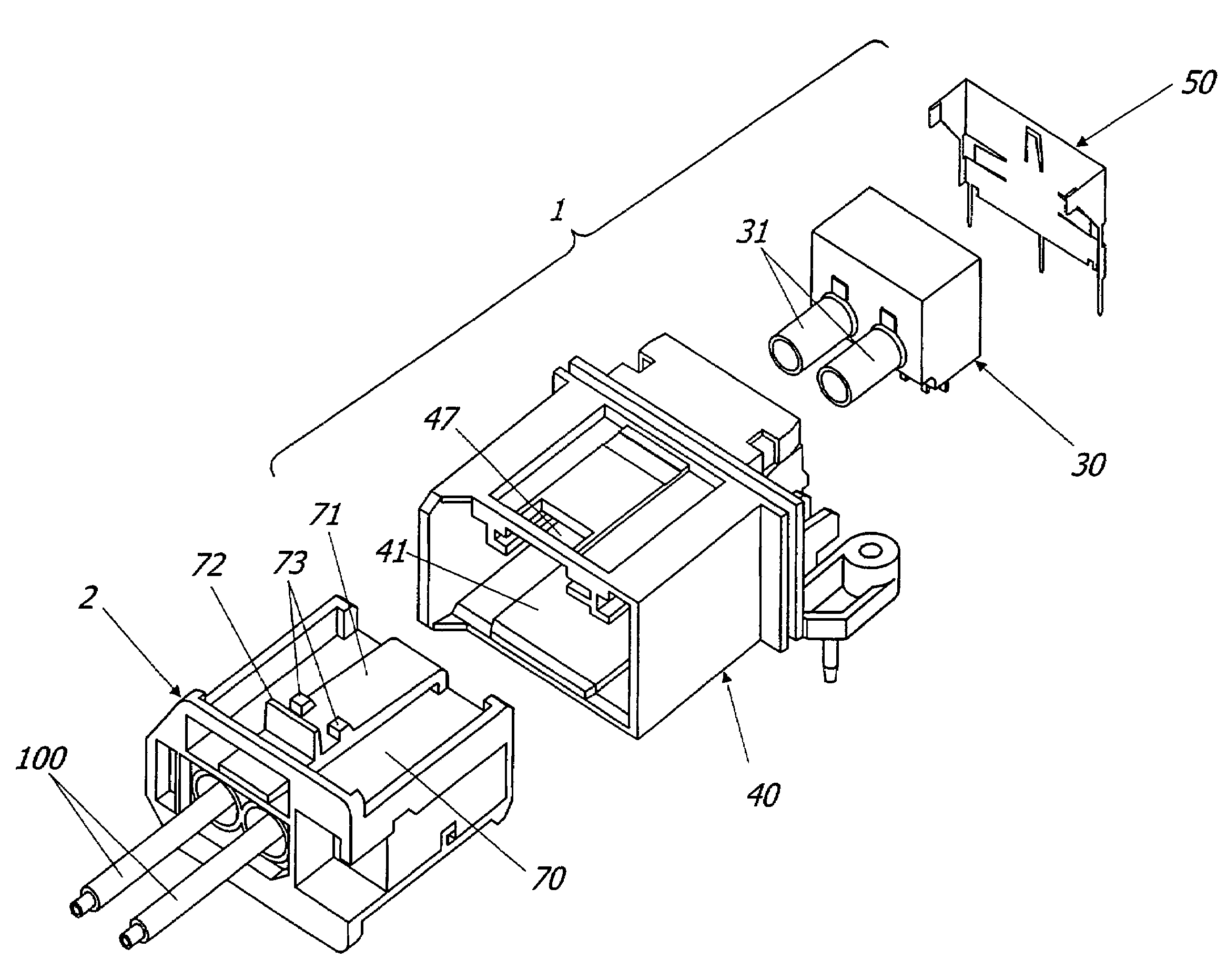
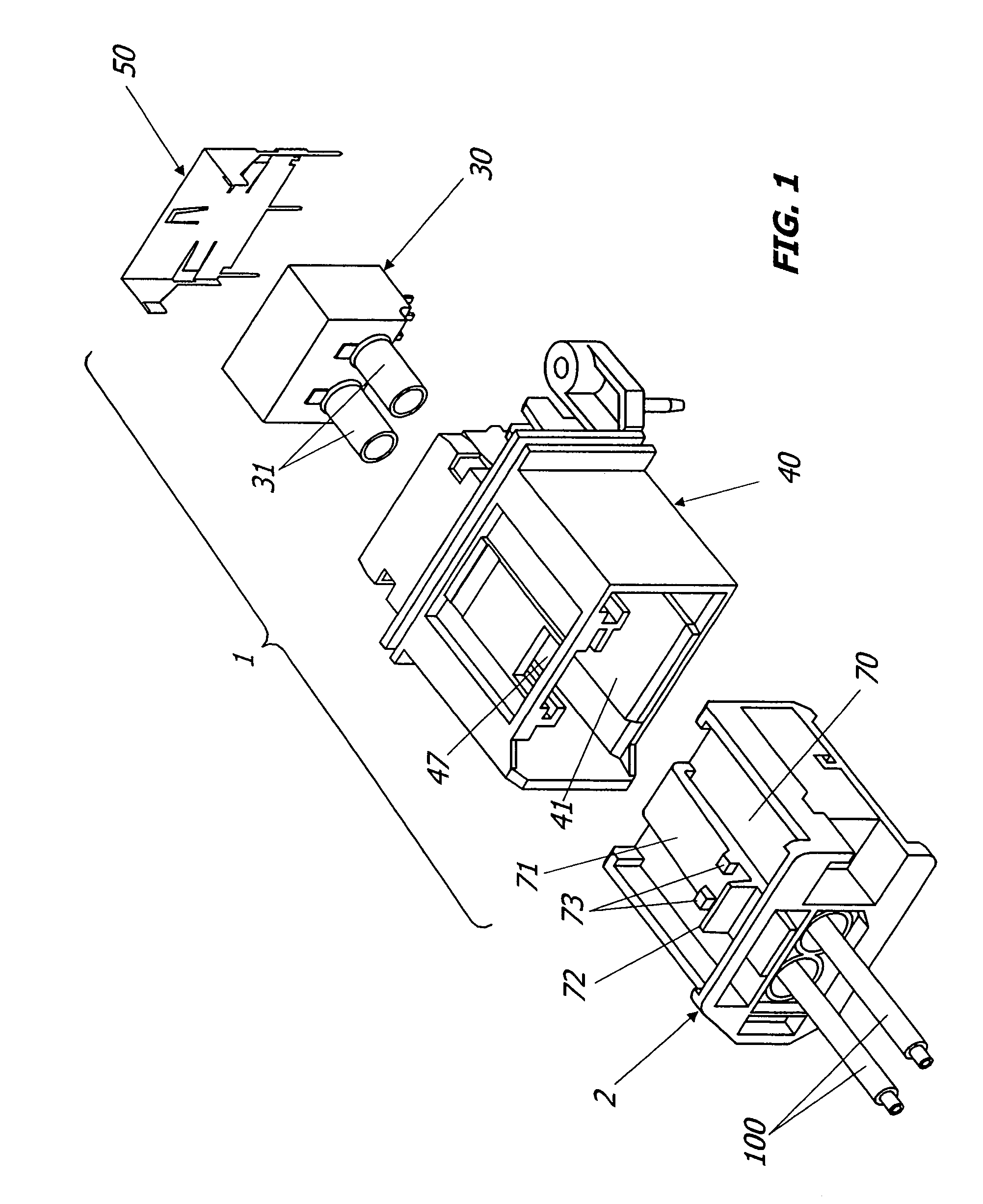
[0045]As shown in FIG. 1, the optical receptacle 1 of this embodiment is connectable with an optical plug 2 supporting one ends of a pair of plastic optical fibers (POF) 110 as an optical transmission medium, and preferably used for data communication between a data base connected through the other ends of the optical fibers 110 and an on-board electric equipment such as CD, DVD, GPS and car telephone.

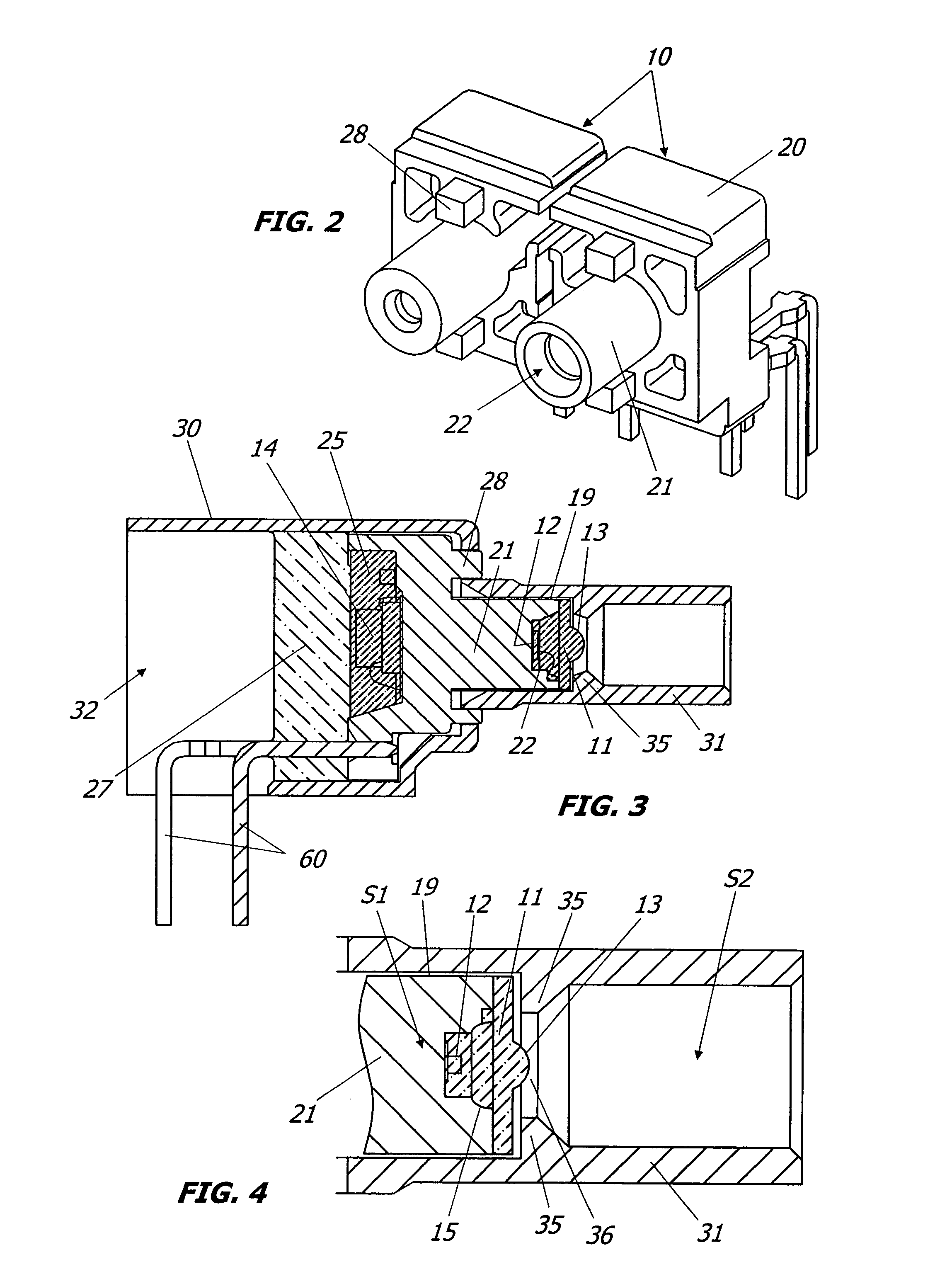
[0046]As shown in FIGS. 1 and 2, the optical receptacle 1 is mainly composed of a pair of photoelectric conversion modules 10 each having the capability of making photoelectric conversion between light signals transmitted through the optical fibers 100 and electrical signals used in the electrical equipment, a module housing 30 of a resin molded article for accommodating the photoelectric conversion modules 10 therein, a receptacle housing 40 for accommodating the modul...


PUM


Abstract

An optical receptacle with low transmission loss, which is connectable with an optical plug, is provided. The optical receptacle includes a photoelectric conversion module having the capability of making photoelectric conversion between light signals and electrical signals, and a module housing. The photoelectric conversion module is a molded interconnect device (MID), which is provided with a module body having a post, an optical device mounted on the post, and an electrical circuit mounted on the module body. The module housing has a tubular projection, into which an end of the optical fiber supported by the optical plug can be inserted. When the optical plug is connected with an optical receptacle, the end of the optical fiber is positioned in the tubular projection so as to be in a closely opposing relation to the optical device mounted on the post.

Description

TECHNICAL FIELD[0001]The present invention relates to an optical receptacle connectable with an optical plug having a light transmitting medium such as an optical fiber, and a photoelectric conversion module for the optical receptacle, which has the capability of making photoelectric conversion between light signals transmitted through the optical transmission medium and electrical signals.BACKGROUND ART[0002]Worldwide developments of high-speed communication system preferably used for transport means such as automobiles, airplanes, trains and shipping are now underway. For example, “MOST®” (Media Oriented System Transport) has been proposed as an optical communication standard in Europe.[0003]FIG. 18 shows a conventional optical connector designed under the “MOST®” standard (“TYCO Electronics & MOST” in Presentations by MOST members on “All Members Meeting Apr. 3, 2001”). This connector is composed of an optical receptacle 1P built in an electronic equipment such as CD, DVD, GPS th...

Claims


Application Information

Patent Timeline
Patent Type & Authority Patents(United States)
IPC IPC(8): G02B6/36G02B6/38G02B6/42
CPCG02B6/4292G02B6/4246G02B6/389G02B6/4204
Inventor KAMBE, YOSHIAKISHIMAYA, KENICHISHIMOMURA, TSUTOMUHAACK, ALBRECHTHALBACH, PAUL GERHARDGAERTNER, MARKUS
Owner MATSUSHITA ELECTRIC WORKS LTD
Why Eureka
Eureka Blog
Learn More