Medical devices with retractable needle

a technology of retractable needles and medical devices, which is applied in the field of retractable needle systems, can solve the problems of no means disclosed to protect users, fingers can be pricked, and the insertion needle is usually very thin and hard to see, so as to prevent the injury or transmission of any dangerous viruses, easy and safe to discard, and easy to manufacture

Inactive Publication Date: 2006-08-15
MDC INVESTMENT HLDG
View PDF71 Cites 76 Cited by
  • Summary
  • Abstract
  • Description
  • Claims
  • Application Information

AI Technical Summary

Benefits of technology

[0035]The present invention is embodied in an approved hypodermic syringe system and intravenous catheter insertion device which is entirely safe prior to insertion or sampling due to a protective cover tip. Furthermore, after insertion or sampling, the hypodermic syringe system and intravenous catheter insertion device is entirely safe, since the health care provider, using one hand, can retract the insertion needle into a tamperproof isolation container which may then be easily and safely discarded, preventing the injury or transmission of any dangerous viruses or bacteria. In addition, both the hypodermic syringe system and intravenous catheter insertion device are easily manufactured, easy to use and provides visual and audible confirmation that the insertion needle has been safely retracted after use.
[0036]More particularly, the hypodermic injection system comprises a cylindrical syringe housing assembly, holding a retractable injection needle which can be safely, quickly and easily retracted within a specially designed syringe plunger. Furthermore, preferably the plunger is fixedly held after use within a specifically designed syringe barrel. The syringe barrel, plunger and needle assembly can be easily discarded without the dangers associated with an exposed needle or needle that can be easily uncapped. The needle is preferably held locked inside the barrel which is tamperproof.

Problems solved by technology

Additionally, the insertion needle is usually very thin and hard to see, especially in low-light conditions.
However, upon removal and placing the needle cap back onto the needle, the fingers can be pricked by a slight visual miscalculation or by a motorneuro mistake.
No means is disclosed for protecting the user from accidental pricking with the tip of the needle.
However, means is provided wherein subsequent retraction of the plunger assembly is inhibited to prevent further loading and use of the syringe.

Method used


Image

  • Medical devices with retractable needle
  • Medical devices with retractable needle
  • Medical devices with retractable needle

Examples


fifth embodiment

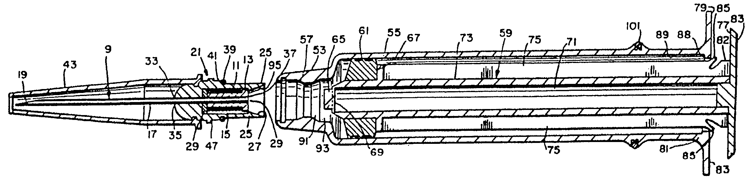
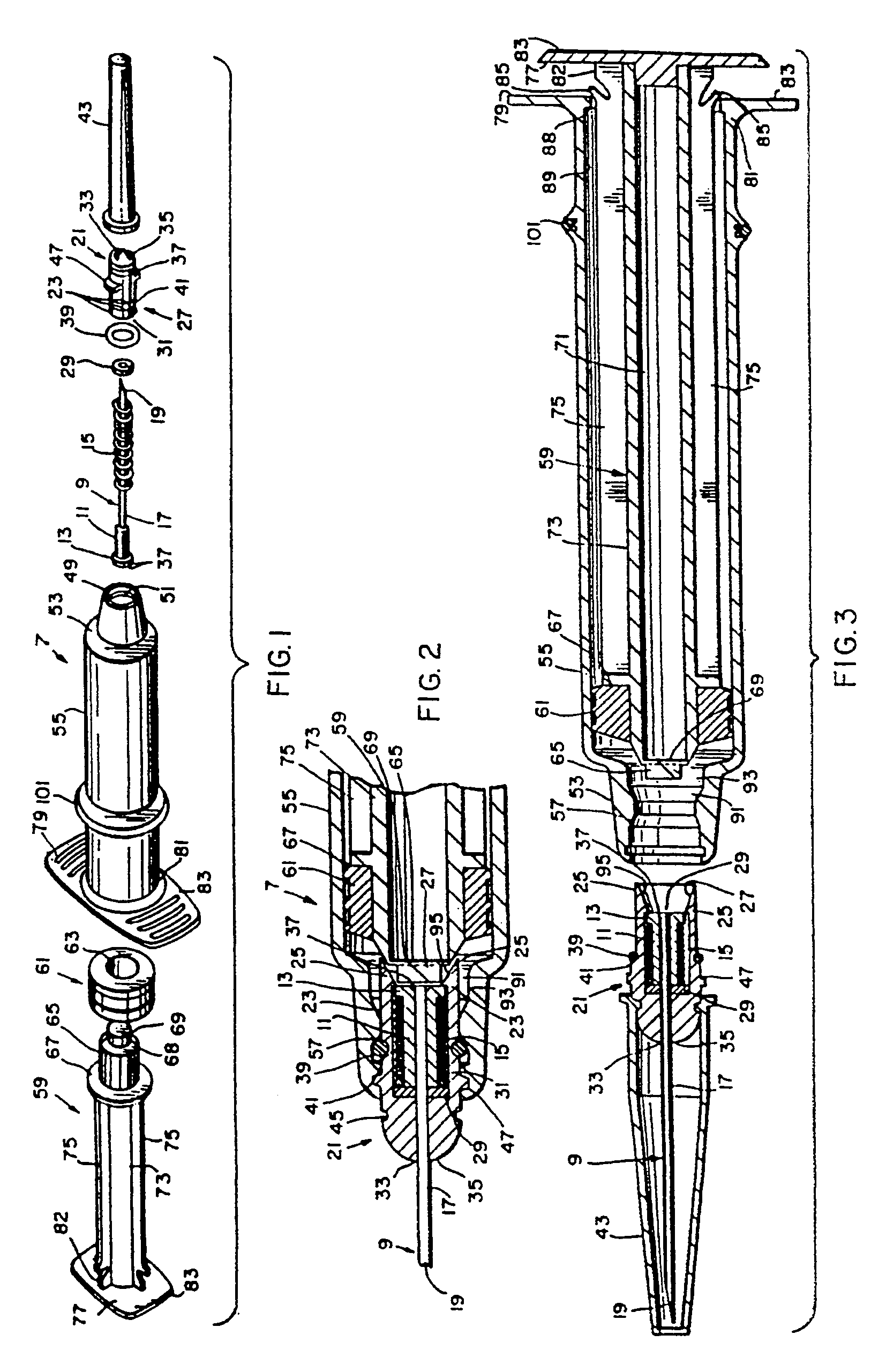
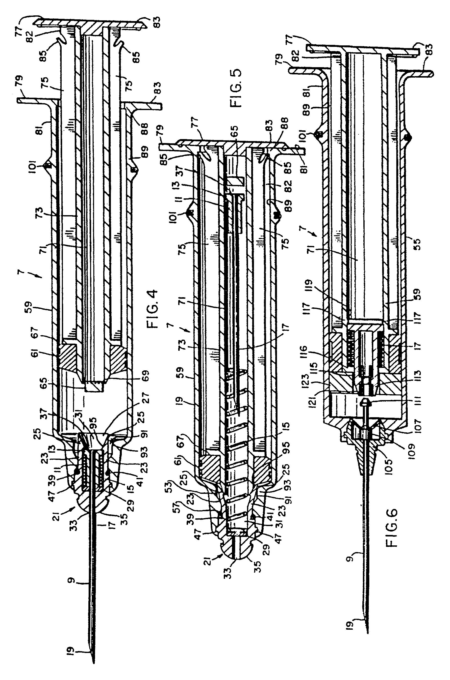
[0056]The best mode for carrying out the invention is presented in the terms of a preferred, second, third, fourth and All five embodiments are similar in principle and function, however, variations in structure segregate the five. The preferred embodiment is shown in FIGS. 1–6, wherein like numerals represent like elements throughout, the complete hypodermic syringe 7 of this embodiment is best shown in exploded view as FIG. 1. The main components of syringe 7 are a standard injection needle 9 having a specifically mounted holder 11 including an enlarged lip 13, located posteriorly thereto. A coiled spring 15 rides a shaft 17 of the injection needle 9 with an axially located passageway 19 therethrough. A cylindrical spring housing 21 includes a plurality of radial spaced resilient fingers 23 which include inwardly engaging inferiorly positioned hooks 25 on the posterior end 27 of the spring housing 21. A sealing means or washer 29 is sized to be received within an inner cavity 31 ...

third embodiment

[0079]the invention is illustrated in FIGS. 7–9 and consists of a syringe barrel 55′ having a partially open end 125 and a fully opened end 127. The barrel 55′ has finger retaining lips 79′ on the partially opened end 125 providing a gripping surface for the user's fingers. Optionally, near the lips 79′, a color coded ring 101 of sufficient resiliency and diameter is slid over the exterior surface of the barrel 55′ and retained by friction to identify the particular syringe system. The open end 125 of the barrel contains bayonet slots 49′ and grooves 51′ or threads for connecting other elements to the open end. The barrel 55′ is transparent thus permitting the user to see the fluid inside, allowing expulsion of bubbles of air that may be within the liquid dispensed by the syringe.

[0080]A hollow syringe plunger 59′ is slidably received within the barrel 55′ and is sized to move linearly back and forth without restriction. The plunger 59′ has converging taper 135 on one end and an axi...

fourth embodiment

[0085]In the invention, the injection needle retracting mechanism is basically the same and the functional principal is identical except that instead of using the syringe 7″ for injecting fluids such as intramuscular absorbing medication or intravenous pharmaceuticals, the invention is directed to removing a fluid sample such as blood from the body. The usual method to accomplish this procedure is to employ a system that includes a hypodermic needle and a barrel including an interconnecting needle that pierces a vacuum container or vial drawing the sample into the container when the connection is made. The same problem exists with this system as it exposes a sharp hypodermic needle with only a removable cover for protection. The inside interconnecting needle is of little danger as it is completely surrounded by the barrel and is unaccessible to most parts of the medical practitioner's body, at least without a conscious effort.

[0086]The invention's embodiment for a device used in tak...


PUM


Abstract

A hypodermic injection system with a retractable needle wherein the needle retracts within an interior cavity of a syringe plunger, such that the needle is confined within the plunger. A spring biases the needle rearwardly into the plunger, and a needle retainer releasably retains the needle against the bias of the spring. The plunger has a frangible end, which dissociates when the plunger engages the needle retainer, allowing the coiled spring to eject the needle into the interior cavity of the plunger. A body fluid sampling embodiment employs the same functional elements except the plunger is shorter and contains a linking that communicates with a vacuum container. The container allows fluid sampling and provides the structure to release the spring retracting the needle. The retractable needle embodiment is also employed with an insertion needle that guides a catheter tube below the skin of a patient and into the vein, and allows retraction of the insertion needle thereby avoiding accidental pricking of the health care worker by the insertion needle.

Description

CROSS REFERENCE TO RELATED APPLICATION[0001]This application is a continuation of U.S. application Ser. No. 09 / 170,649 filed Oct. 13, 1998 now U.S. Pat. No. 6,179,812, which is a continuation of U.S. application Ser. No. 08 / 692,895 filed Jun. 20, 1996 now U.S. Pat. No. 6,096,005, which is a continuation-in-part of U.S. application Ser. No. 08 / 381,203 filed Jan. 31, 1995, now abandoned, which is a continuation of U.S. application Ser. No. 08 / 127,962 filed Sep. 27, 1993, now U.S. Pat. No. 5,407,431, which is a continuation-in-part of U.S. application Ser. No. 08 / 017,832 filed Feb. 16, 1993, now abandoned, which is a continuation of U.S. application Ser. No. 07 / 656,305 filed Feb. 15, 1991, now U.S. Pat. No. 5,188,599, which is a continuation-in-part of U.S. application Ser. No. 07 / 378,275, filed Jul. 11, 1989, now U.S. Pat. No. 4,994,034. Each of the foregoing applications is hereby incorporated herein by reference as if fully set forth herein.FIELD OF THE INVENTION[0002]This invention...

Claims


Application Information

Patent Timeline
Patent Type & Authority Patents(United States)
IPC IPC(8): A61M5/00A61M5/32A61B5/145A61B5/15A61M5/31A61M5/50A61M25/06
CPCA61B5/154A61M5/3129A61M5/3234A61M5/5013A61M25/0631A61B5/15003A61B5/150519A61B5/150572A61B5/150648A61B5/150732A61B5/1444A61B5/1438A61M5/3202A61M5/502A61M5/508A61M25/0612A61M2005/3231A61M2005/3235A61M2205/583A61M2205/6081A61M2005/3241A61B5/150351A61B5/150389
Inventor BOTICH, MICHAEL J.HALSETH, THOR R.
Owner MDC INVESTMENT HLDG
Why Eureka
Try Eureka