Method and apparatus for plasma generation

a plasma generator and plasma technology, applied in the field of ionization sources, can solve the problems of low ionization amount, process instability, and limited use of equipment using radioactive ionization sources, and achieve the effects of reducing device performance or output intensity, and low to moderate ionization energy

Inactive Publication Date: 2006-08-15
DH TECH DEVMENT PTE
View PDF106 Cites 44 Cited by
  • Summary
  • Abstract
  • Description
  • Claims
  • Application Information

AI Technical Summary

Benefits of technology

[0006]RF discharge ionization reduces some of these disadvantageous effects. RF discharges are subdivided into inductive and capacitive discharges, differing in the way the discharge is produced.
[0007]Inductive methods are based on electromagnetic induction so that the created electric field is a vortex field with closed lines of force. Inductive methods are used for high-power discharges, such as for production of refractory materials, abrasive powders, and the like.
[0008]Capacitive discharge methods are used to maintain RF discharges at moderate pressures p˜1–100 Torr and at low pressures p˜10−3–1 Torr. The plasma in them is weakly ionized and non-equilibrium, like that of a corona discharge. Moderate-pressure discharges have found application in laser technology to excite CO2 lasers, while low-pressure discharges are used for ion treatment of materials and in other plasma technologies.
[0009]Another ionization process is UV ionization. This process is sometimes referred to as atmospheric pressure photo-ionization (APPI). In low pressure conditions, photo-ionization involves direct interaction of photons with samples, forming positively charged molecular ions and free electrons. At elevated pressure conditions, the situation is not so simple and the ionization process for sample molecules can include a sequence of gas phase reactions, the details of which depend on the energetic properties of initially formed ions and free electrons (due to direct photo-ionization) and on the nature of the ambient gas.
[0010]One disadvantage of UV ionization is that it provides low to moderate ionization energies. This limits the types of molecules that can be ionized. As well, sometimes APPI can give unexpected results. The photons are typically generated in a tube, with the photons passing through a window, and this window material affects efficiency. Also, the surfaces of the UV devices can become contaminated or coated from the ionization product, which can degrade device performance or output intensity. As well, the UV tubes can be delicate and fragile, and hence are generally not suitable to operation in harsh environments or in applications requiring a significant amount of manual handling.SUMMARY OF THE INVENTION
[0011]The invention, in various embodiments, addresses the deficiencies in the prior art by providing reliable non-radioactive ionization sources for various applications. More particularly, in one aspect, the invention provides a capacitive discharge apparatus for generating a stable plasma at pressures including at or around atmospheric pressure.

Problems solved by technology

However, because of the potential health hazard and need for regulation, wide-spread use of equipment using radioactive ionization sources has been limited.
And even though smoke alarms use radioactive sources, the amount of ionization is low, and they still require government regulation.
However, this process is not stable and can contaminate the sample with metal ions or NOx, as would interfere with analytical results.
One disadvantage of UV ionization is that it provides low to moderate ionization energies.
This limits the types of molecules that can be ionized.
As well, sometimes APPI can give unexpected results.
The photons are typically generated in a tube, with the photons passing through a window, and this window material affects efficiency.
Also, the surfaces of the UV devices can become contaminated or coated from the ionization product, which can degrade device performance or output intensity.
As well, the UV tubes can be delicate and fragile, and hence are generally not suitable to operation in harsh environments or in applications requiring a significant amount of manual handling.

Method used


Image

  • Method and apparatus for plasma generation
  • Method and apparatus for plasma generation
  • Method and apparatus for plasma generation

Examples


embodiment 10

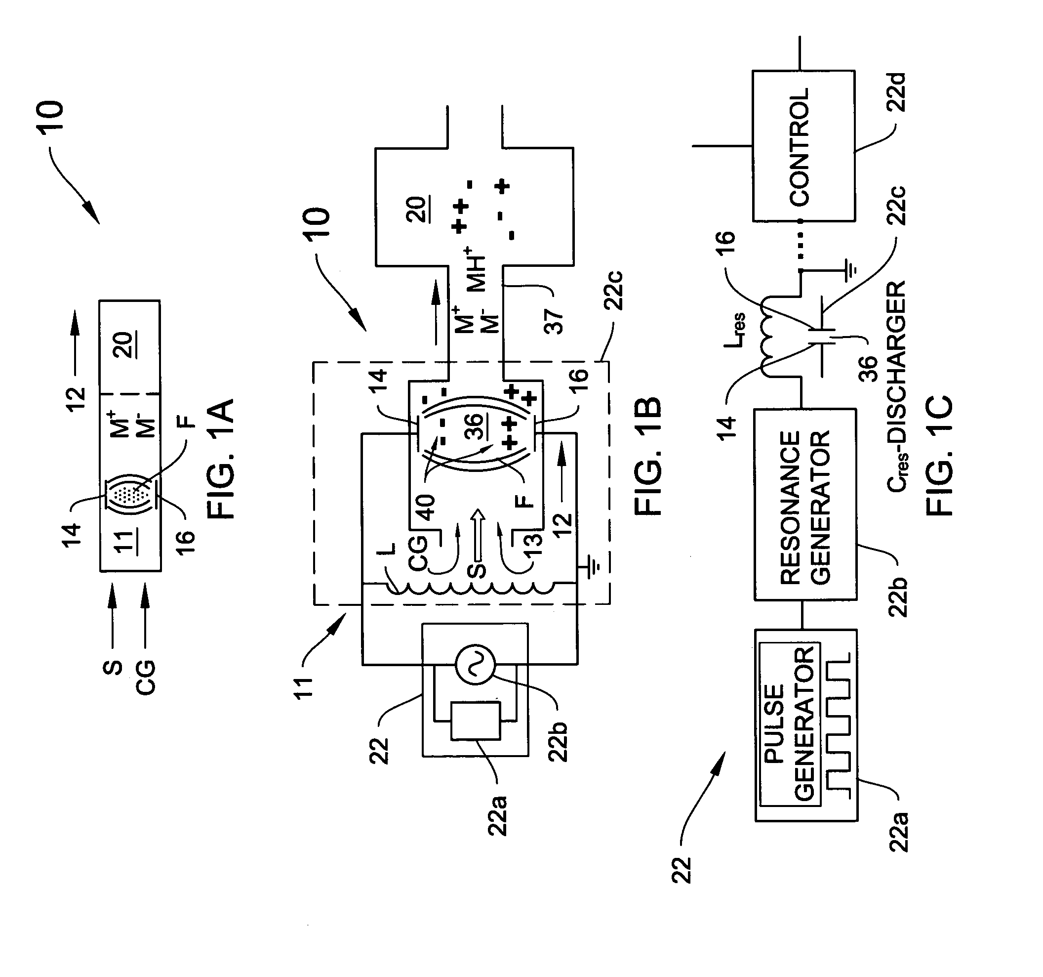
[0135]FIG. 20F shows a plural channel embodiment 10 of the invention, including a first flow channel 270 having a plasma ionizer 11, which receives the gas flow CG and generates the ions ++,−−. These ions flow into an ion diverter, which may be a baffle or another gas flow, to influence and redirect the ion flow. Preferably, the diverter is selective. For example, FIG. 20F includes a diverter 271, which diverts selected ions into second flow channel 272 through opening 273. The remaining flow and other by-products of the plasma ionization process are exhausted out of flow channel 270 at vent 280.

[0136]The diverter may also be a biased electrode. In one embodiment, as shown in FIG. 20F, diverter 271 includes first and second electrodes 274 and 275 which are independently biasable. In one illustration, electrode 274 is negatively biased which drives the negative ions −−,−− generated in the plasma ionization part 11 through access 273 into a sample ionization section 276 in the second ...

embodiment 700

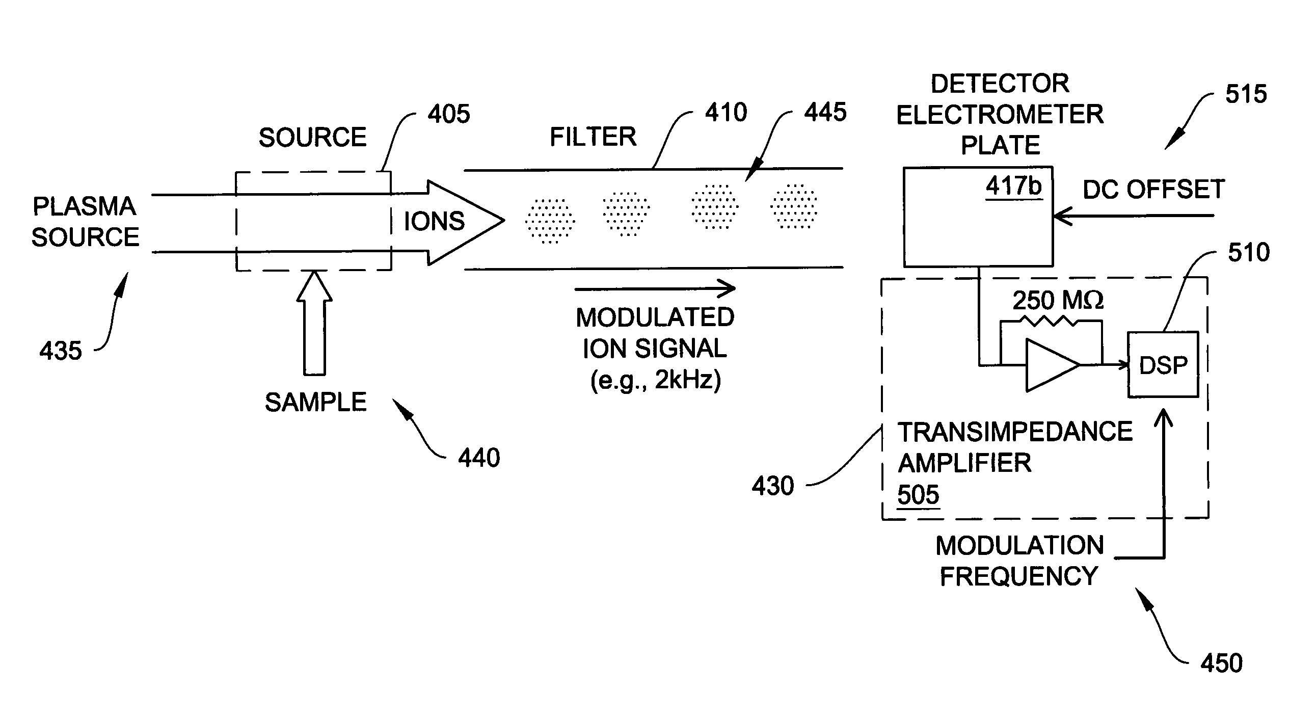
[0185]Because of the packetized nature of the ion production, other information may also be gleaned through use of this technique. For example, in the embodiment 700 of FIG. 30, a waveform of the drive signal 705 and detection signal 710 can be compared against one another in the DSP on the rising edge or falling edge to determine a “time of flight” (TOF) of the ions from the ionization source 405 to the detector 415, which provides useful detection information like that obtained in known TOF ion mobility spectrometers. A DMS filter drive according to an illustrative embodiment of the invention will now be discussed. There is a need for efficient DMS filter drive circuit designs as may be desirable for faster and more reliable operation, especially in the context of hand-held and battery-operated applications. Moreover, traditional designs typically exhibit poor efficiency due to the effects of both parasitic and load capacitances. As discussed below, the invention, in various illus...


PUM


Abstract

An RF-driven plasma source, including a pair of spaced-apart plasma electrodes, wherein the electrodes act as plates of a capacitor, the gas electrically discharges and creates a plasma of both positive and negative ions, in a clean process that enables efficient sample analysis, with preferred isolated sample photo-ionization, reduced-power operation and also including signal detection with modulated drive electronics.

Description

REFERENCE TO RELATED APPLICATIONS[0001]This application is a continuation-in-part of U.S. patent application Ser. No. 10 / 215,251 (filed 7 Aug. 2002). the entire contents of which are incorporated herein by reference, which claims priority to and the benefit of the following applications: U.S. Provisional Patent Application 60 / 310,902 (filed 8 Aug. 2001): U.S. Provisional Patent Application 60 / 335,219 (filed 25 Oct. 2001); U.S. Provisional Patent Application 60 / 340,815 (filed 12 Dec. 2001); and U.S. Provisional Application 60 / 388,052 (filed 12 Jun. 2002). This application claims priority to and the benefit of, and incorporates by reference, the following applications: U.S. Provisional Patent Application 60 / 488,019 (filed 17 Jul. 2003); U.S. Provisional Application 60 / 498,163 (filed 27 Aug. 2003); U.S. Provisional Patent Application 60 / 498,093 (filed 27 Aug. 2003); and U.S. Provisional Patent Application 60 / 518,367 (filed 8 Nov. 2003). This application claims priority to and the benef...

Claims


Application Information

Patent Timeline
Patent Type & Authority Patents(United States)
IPC IPC(8): B01D59/44H01J49/12H01J49/40
CPCH05H1/24G01N27/624H05H1/2406H05H1/246
Inventor MILLER, RAANAN A.NAZAROV, ERKINJON G.KRYLOV, EVGENYEICEMAN, GARY A.WRIGHT, JOHN A.KENDIG, STEPHEN D.MORRIS, C. JAMESCAMERON, DOUGLAS B.
Owner DH TECH DEVMENT PTE
Why Eureka
Try Eureka