Method of monitoring and controlling the seating of screws to the optimum point of grip independent of screw size and material density

a technology of screw seating and screw size, applied in the direction of motor/generator/converter stopper, dynamo-electric converter control, osteosynthesis device, etc., can solve the problems of poor accuracy and repeatability, wear and tear of the clutch over time, etc., to reduce the rate of torque change, eliminate the need for configuration of the tool, and smooth the effect of torque rise and fall

Active Publication Date: 2006-08-15
INTELLIGENT AUTOMATION DESIGN
View PDF36 Cites 59 Cited by
  • Summary
  • Abstract
  • Description
  • Claims
  • Application Information

AI Technical Summary

Benefits of technology

[0006]To avoid the above and other problems, the present invention is directed to a method of seating screws (107) to the optimum point of grip by stopping the motor (106) when a decrease in the rate of change of torque is realized. By averaging torque readings, the controller (100) smoothes the torque rise and falls that occur due to inconsistencies in the material and screw (107). This in turn, eliminates the possibility of a false decrease in the rate of change stopping the motor (106) when it is not fully

Problems solved by technology

There are a number of problems associated with the use of clutches in screw (107) seating.
As mec

Method used


Image

  • Method of monitoring and controlling the seating of screws to the optimum point of grip independent of screw size and material density
  • Method of monitoring and controlling the seating of screws to the optimum point of grip independent of screw size and material density
  • Method of monitoring and controlling the seating of screws to the optimum point of grip independent of screw size and material density

Examples


Embodiment Construction

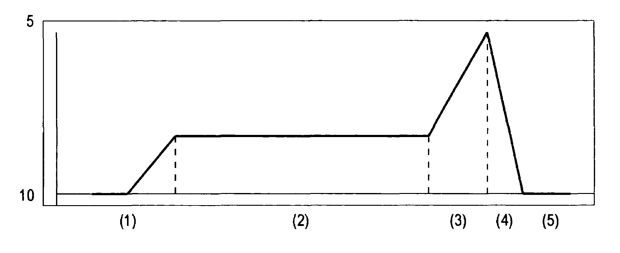
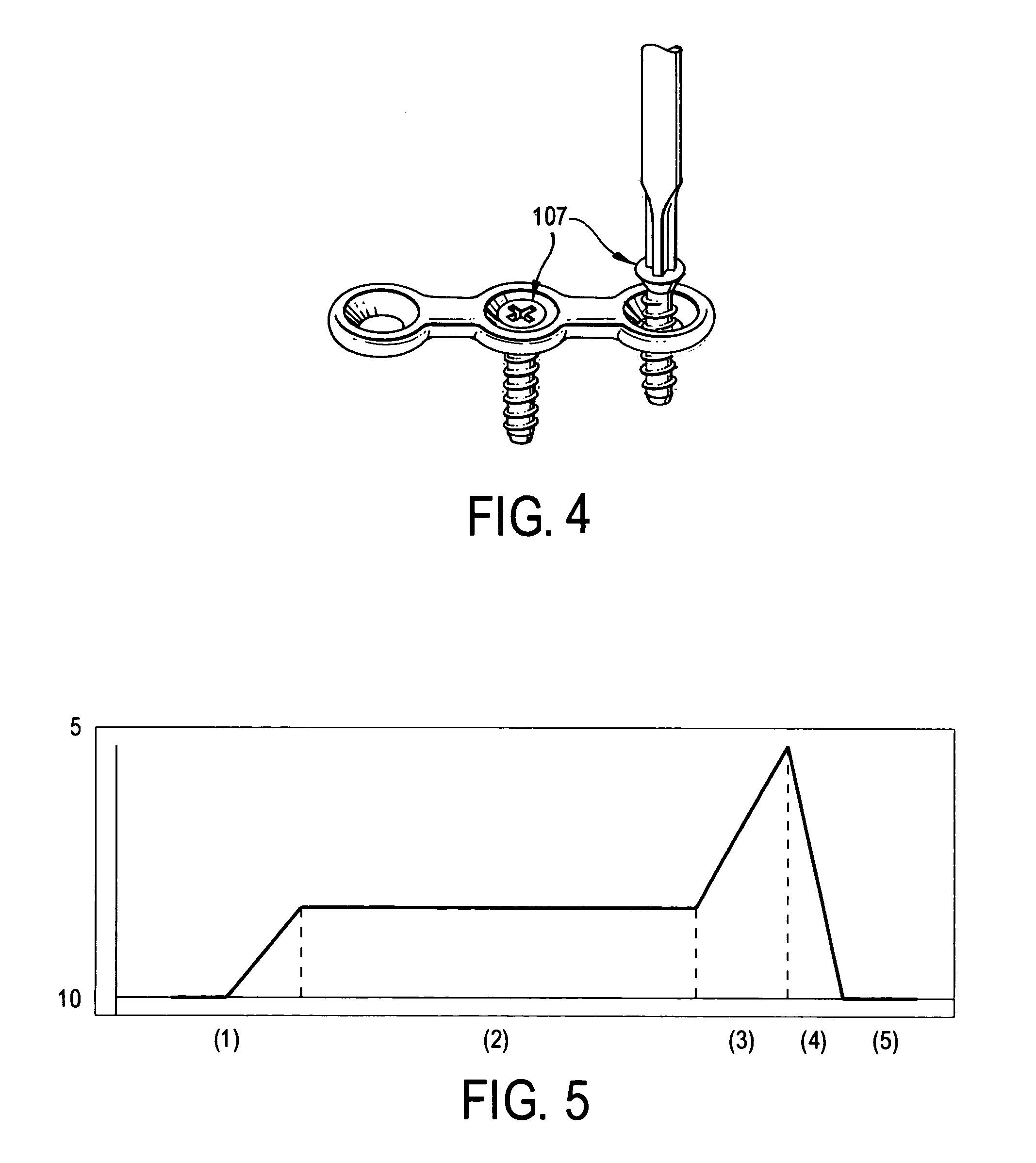
[0014]In the preferred embodiment, the torque is controlled in the following manner, which will be explained with reference to FIG. 5. The seating torque profile shown in FIG. 5 can be divided into the following zones.

[0015]Zone 1: The screw (107) tip makes contact with the material and the required torque level ramps up until the barrel of the screw (107) is reached.

[0016]Zone 2: The barrel of the screw (107), which is of a relatively constant diameter, requires a constant torque to continue driving the screw (107) into the material.

[0017]Zone 3: Once the barrel is seated into the material, the torque required to continue driving the screw (107) rises significantly as the head of the screw (107) comes in contact with the material. The required torque to turn the screw (107) continues to rise until the optimum point of grip is reached, which occurs at the transition point from zone 3 to zone 4.

[0018]Zone 4: In zone 4, the torque required to continue turning the screw (107) drops sig...


PUM


Abstract

A method of controlling a motor (106) used to drive a screwdriver bit (105) such that screws (107) are seated to the optimum point of grip between the screw (107) and the work piece material. An electronic control circuit controls the speed and output torque of the motor (106). The control system utilizes pulse width modulation (PWM) to control motor (106) speed and torque. The PWM signal controls the duty cycle of the transistors that supply current to the motor (106). The amount of current flowing through the motor (106) coils is proportional to the amount of torque the motor (106) is producing. Motor (106) current is measured as voltage produced across a precision resistor that is in series with the motor (106) coils. As the current in the motor (106) increases, the voltage across the resistor increases (V=IR). To accurately measure the torque, as measured by the voltage across the precision resistor, a capacitor with a resistor and/or a diode is used to average the analog signal that is measured by the microprocessor. The microprocessor further filters the analog signal using an averaging formula to produce a stable value corresponding to motor (106) torque/current. When a decrease in current, corresponding to a drop in torque, is detected at the optimum point of grip, the controller (100) stops the motor (106).

Description

REFERENCE TO RELATED APPLICATION[0001]The present application claims the benefit of U.S. Provisional Patent Application No. 60 / 513,544, filed Oct. 24, 2003, whose disclosure is hereby incorporated by reference in its entirety into the present disclosure.FIELD OF THE INVENTION[0002]The present invention is directed to a method of monitoring and controlling the seating of screws and more particularly to such a method which minimizes or avoids stripping.DESCRIPTION OF RELATED ART[0003]When using screws (107) to fasten two materials together, the objective is to stop turning the screw (107) when the optimum point of grip is achieved between the two materials and the screw (107). The torque required to seat the screw (107) increases as the screw (107) passes through the various zones of the seating process. Once the optimum point of grip is reached, the torque required to continue turning the screw (107) decreases rapidly as the screw (107) enters the strip or material yield zone.[0004]T...

Claims


Application Information

Patent Timeline
IPC IPC(8): H02P7/00
CPCA61B17/8875B25B23/147B25B23/14A61B17/1626A61B2019/464A61B2019/301A61B2090/064A61B2090/031
Inventor SMITH, MARKWHYTE, JOSEPH
Owner INTELLIGENT AUTOMATION DESIGN
Why Eureka
Try Eureka