Supercharge Your Innovation With Domain-Expert AI Agents!

BTL amplifier apparatus

a technology of amplifier apparatus and balance transformer, which is applied in the direction of amplifier combinations, electrical transducers, gain control, etc., can solve the problems of voice coil damage caused by distortion, and achieve the effect of not damage to the voice coil of the speaker

Inactive Publication Date: 2006-08-15
PIONEER CORP
View PDF9 Cites 13 Cited by
  • Summary
  • Abstract
  • Description
  • Claims
  • Application Information

AI Technical Summary

Benefits of technology

[0010]An object of the present invention is to provide an improved BTL amplifier apparatus which will not damage the voice coil of a speaker.
[0014]In accordance with the present invention, since the differential voltage is detected to provide a DC offset while the input signal is not supplied to the power amplifiers, using a decision result of the difference voltage, it is possible to prevent a voice coil of the speaker from being damaged.
[0015]In accordance with the present invention, the period while the input signal to be supplied to the power amplifiers is muted can be set when it is required to provide the DC offset. During the period, the detection and decision can be carried so that a sense of discomfort is not given to listeners.

Problems solved by technology

However, if the capacitor 3 is deteriorated to generate a leak current and the BTL amplifier 1 is deteriorated, a DC current flows through a voice coil of a speaker so that the voice coil may be damaged by the generated distortion.

Method used


Image

  • BTL amplifier apparatus
  • BTL amplifier apparatus
  • BTL amplifier apparatus

Examples


first embodiment

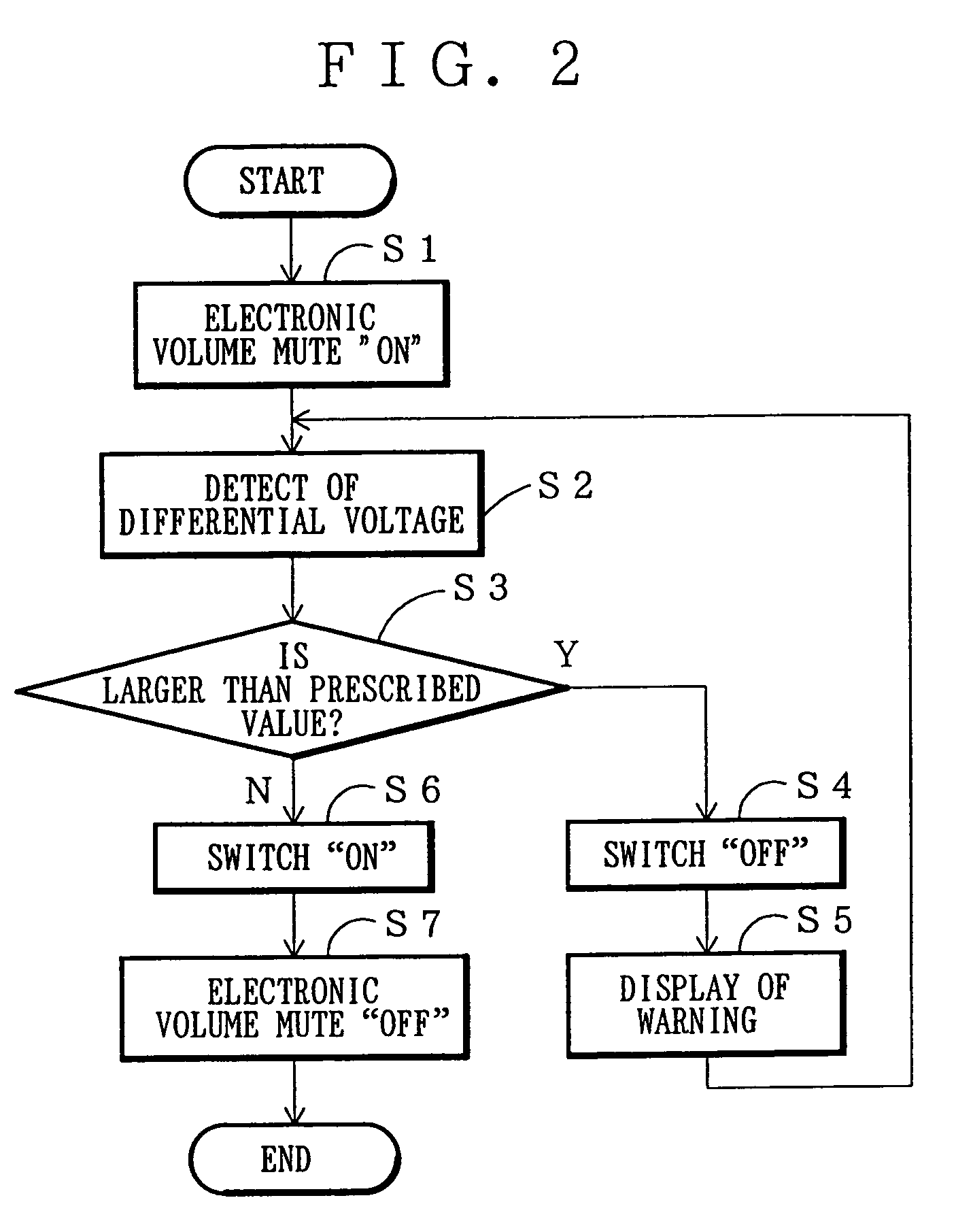
[0029]Referring to FIG. 2, an explanation will be given of the operation of the BTL amplifying apparatus according to the present invention.

[0030]When a power switch turns on, a signal source is switched, or a command is issued as necessary, the operation starts.

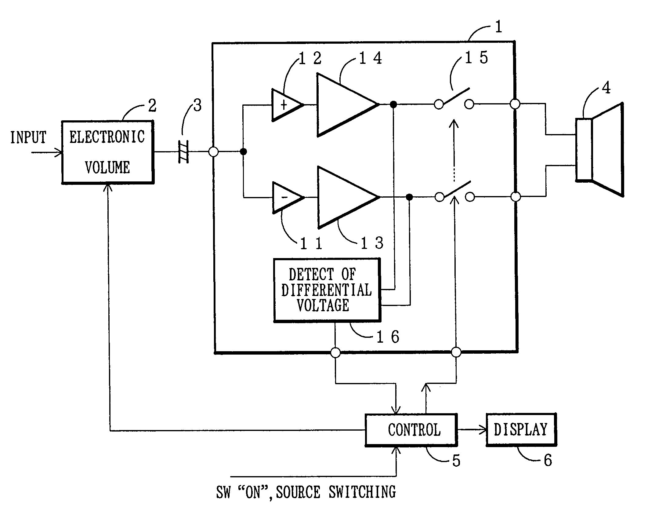
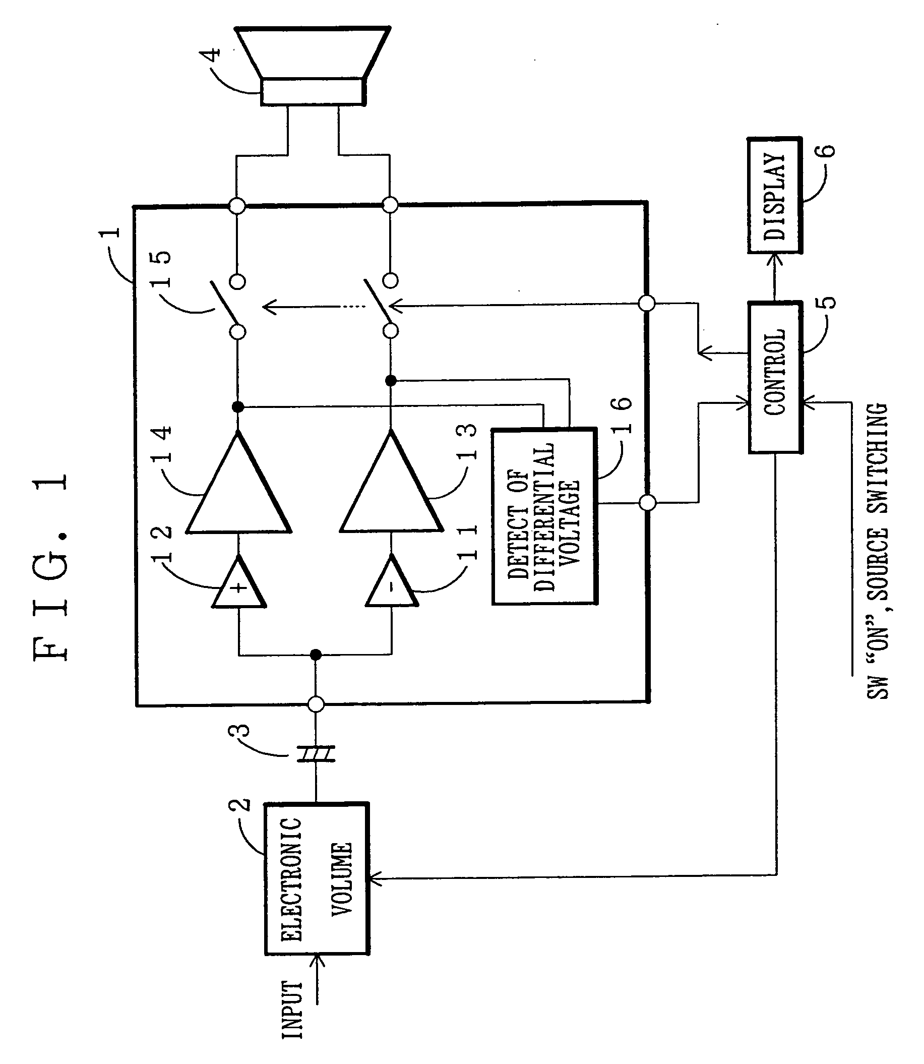
[0031]In step S1, a control unit 5 sends a command of “muting” to the electronic volume 2 to make the output therefrom zero.

[0032]In step S2, the control unit 5 reads the differential voltage detected by the differential voltage detecting unit 16.

[0033]Now, since the audio signal is not supplied from the electronic volume 2, the control unit 5 produces the difference between the DC voltages from the power amplifiers 13 and 14, i.e. DC offset.

[0034]In step S3, the control unit 5 decides whether or not the differential voltage read in step S2 is larger than a prescribed value. If the answer is “YES”, the processing proceeds to step S4. If the answer is “NO”, the processing proceeds to step S6.

[0035]In step S4, the control unit...

third embodiment

[0044]FIG. 4 shows the configuration of third embodiment of the BTL amplifier apparatus according to the present invention. In this embodiment, the power amplifiers 13 and 14 are provided with activation / deactivation circuits 18 and 19 for activating or deactivating these power amplifiers, respectively. Each activation / deactivation circuit is constructed as a switch for turning on / off the signal passing through the power amplifier or so as to control the supply of a power source voltage to the power amplifier.

[0045]In this embodiment, when it is decided that the differential voltage is larger than a prescribed value, the activation / deactivation circuits 18, 19 deactivate the power amplifiers 13, 14 so that the signals are not supplied to the speaker 4.

fourth embodiment

[0046]FIG. 5 shows the configuration of fourth embodiment of the BTL amplifier apparatus according to the present invention.

[0047]In this embodiment, as seen from FIG. 5, the electronic volume 2 in FIG. 4 is replaced by a common mechanical volume 20a and a switch 20b connected to the output from the volume 20a.

[0048]In operation, in step S1, the switch 20b is turned on by the control unit 5 so that the signal from the volume 20a is muted. Thereafter, the DC offset is decided in the same processing as described with reference to the previous embodiments described above. It should be noted that the mechanical volume 20a and the switch 20b may be applied to the first embodiment as shown in FIG. 1.

[0049]In each of the embodiments described above, although the control unit 5 is provided outside the integrated circuit 1, it may be provided within the integrated circuit 1. The decision means in step S3 in the control unit 5 may be separately provided within the integrated circuit 1.


PUM


Abstract

A BTL amplifying apparatus has two power amplifiers in an BTL configuration for amplifying a speaker. It includes detection means for detecting a differential voltage between outputs from the two power amplifiers while an input signal to be supplied to the power amplifiers is muted, and decision means for deciding whether or not the differential voltage is larger than a prescribed voltage. Such a configuration prevent the speaker from being damaged.

Description

BACKGROUND OF THE INVENTION[0001]1. Field of the Invention[0002]The present invention relates to a BTL (Balanced Transformer Less) amplifier apparatus for driving a speaker.[0003]2. Description of the Related Art[0004]Generally, the BTL amplifier has various advantages: (1) a high output is obtained from a low power supply voltage, (2) distortion at even order is canceled; (3) the amount of ripple rejection of the power supply is much. For this reason, it has been widely used in an audio system for a vehicle.[0005]FIG. 9 shows a typical conventional BTL amplifier 1 formed in an integrated circuit. The BTL amplifier 1 includes an inverting amplifier 11 for inverting an input signal and amplifiers 13 and 14 each having a gain equal to that of the inverting amplifier 11.[0006]Reference numeral 2 denotes an electronic volume, 3 a coupling capacitor and 4 a speaker.[0007]Nowadays, the BTL amplifier 1 and electronic volume 2 are designed in a semiconductor integrated circuit in which they...

Claims


Application Information

Patent Timeline
Patent Type & Authority Patents(United States)
IPC IPC(8): H04B15/00H03F3/68H03F1/52H03G3/30H04R3/00
CPCH03F1/52H04R3/007H03G3/301
Inventor HASEGAWA, TATSUZOINOHANA, HARUYUKIOZAWA, AKIO
Owner PIONEER CORP
Features
  • R&D
  • Intellectual Property
  • Life Sciences
  • Materials
  • Tech Scout
  • Unparalleled Data Quality
  • Higher Quality Content
  • 60% Fewer Hallucinations
Learn More