Diaphragm for electroacoustic transducer and method of making the same

Inactive Publication Date: 2006-08-15
PIONEER CORP +1
View PDF6 Cites 20 Cited by
  • Summary
  • Abstract
  • Description
  • Claims
  • Application Information

AI Technical Summary

Benefits of technology

[0014]The foam layer is formed using a spring back effect of the fibers. Therefore, the three-layer structure which has the inner foam layer and the sandwiching outer non-foam layers is created without using a foaming agent. The diaphragm having the three-layer structure is lightweight and has high rigidity. Further, the fibers twine three-dimensionally so that the rigidity of the surface layers becomes close to the rigidity of the inner layer, and the rigidity of the material in the resin flow direction during the injection molding process becomes close to the rigidity

Problems solved by technology

No conventional materials meet all of the above mentioned requirements for the diaphragm.
This results in an increase of the manufacturing cost.
The resulting speaker diaphragm is lightweight, and has large internal loss, high rigidity and high environmental resistance.
However, if the three-layer structure is created from the re

Method used


Image

  • Diaphragm for electroacoustic transducer and method of making the same
  • Diaphragm for electroacoustic transducer and method of making the same
  • Diaphragm for electroacoustic transducer and method of making the same

Examples


Embodiment Construction

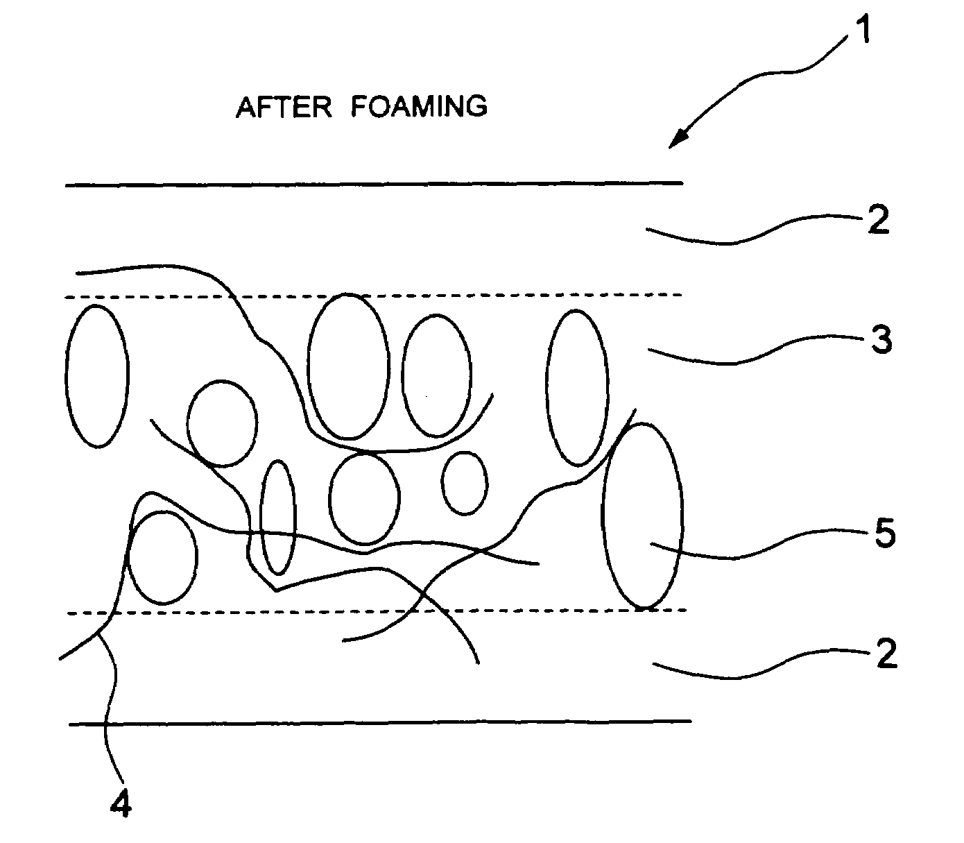
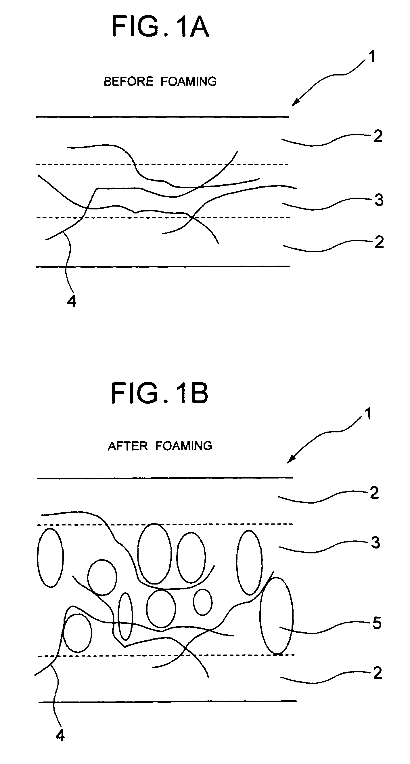
[0020]Embodiments of the present invention will be described in reference to the accompanying drawings. A diaphragm for a speaker will be described as an example of a diaphragm for an electroacoustic transducer according to the present invention. Referring to FIGS. 1A and 1B, a speaker diaphragm 1 has an inner foam layer 3 and opposite surface layers 2. The inner foam layer 3 is produced by the following process: (1) injecting a thermoplastic resin mixture, in a molten state, into a cavity of a metallic mold, wherein the thermoplastic resin mixture includes fibers having relatively high rigidity; and (2) retracting a half of the metallic mold immediately after the step (1) to reduce the pressure inside the cavity, thereby causing a foaming phenomenon in the resin mixture due to a spring back effect of the fibers. Since outer surfaces of the foam layer contact the inner wall of the metallic mold (i.e., cavity wall) while the resin is injected into the metallic mold, the outer surface...


PUM

PropertyMeasurementUnit
Lengthaaaaaaaaaa
Temperatureaaaaaaaaaa
Lengthaaaaaaaaaa

Abstract

A molten resin is injected into a cavity together with long fibers. Opposite surfaces of the resin are solidified as a fiber-resin mixture temperature drops. These surface layers become non-foam layers. A foam layer is created between the non-foam layers. A pressure reduction process is applied to cause a spring back effect when the foam layer is created. A diaphragm having these three layers can be manufactured in an inexpensive process, but physical characteristics and appearances of the diaphragm are not sacrificed.

Description

BACKGROUND OF THE INVENTION[0001]1. Field of the Invention[0002]The present invention relates to a diaphragm used in an electroacoustic transducer such as a speaker, and also relates to a method of fabricating such diaphragm.[0003]2. Description of the Related Art[0004]In general, a material for a diaphragm has to have a small density, large Young's modulus (high rigidity) and appropriate internal loss. Further, the diaphragm material needs to possess a sufficient resistance to the environment.[0005]A typical-material for a conventional diaphragm is PP (polypropylene) which has an adequate environmental resistance (particularly, water resistance) and large internal loss. Another known material for the diaphragm is a liquid crystal polymer which has high rigidity.[0006]One type of diaphragms has a honeycomb structure to increase rigidity and reduce weight. Another type of diaphragms has a three-layer structure that includes a foam and planar skin layers, which sandwich the foam. Amon...

Claims


Application Information

Patent Timeline
IPC IPC(8): H04R25/00G01T1/20A61B6/03C30B28/04C30B30/02C30B30/04G01T1/202
CPCB29C44/0415B29C44/3492H04R31/003H04R7/125B29L2031/3418H04R2307/029H04R2307/025C30B30/04
Inventor HACHIYA, SATOSHISATO, MASATOSHI
Owner PIONEER CORP
Why Eureka
Try Eureka