
Single platform electronic tester

a single platform, electronic tester technology, applied in the direction of testing circuits, instruments, generating/distributing signals, etc., can solve the problems of prior art linear/mixed signal testers having some limited digital testing capability, and no single tester has the performance required to test a broad range of digital ics, analog/mixed signal ics, memory ics,

Inactive Publication Date: 2006-08-15
LTX CORP
View PDF26 Cites 23 Cited by
  • Summary
  • Abstract
  • Description
  • Claims
  • Application Information

AI Technical Summary

Problems solved by technology

One disadvantage of the prior art automatic electronic testers is that no single tester has the performance required to test a broad range of digital ICs, analog / mixed signal ICs, and memory ICs.
The prior art linear / mixed signal testers typically have some limited digital testing capability.
The prior art digital testers typically have some limited analog capability.
Nevertheless, complementary capabilities of both types of testers is extremely limited.
Furthermore, the two types of testers are typically incompatible.
This can result in higher cost of operation because test equipment is underutilized when the device that the tester can exclusively test is not being produced.
As a result, the primary disadvantage of prior art electronic test equipment is that a single platform tester cannot fully test the full spectrum of ICs, including some of the more complex ICs that have a high level of integration, such as some newer system-on-a-chip ICs.
Using two testers is typically relatively expensive, cumbersome, and time consuming as opposed to using a single tester.
Not only is there the added expense of two machines rather than one, but typically corporations have employees who are trained on one type of tester (digital or linear / mixed signal) but not the other, and vice versa.
Furthermore, some tests might be extremely difficult, if not impossible, to perform on two separate testers sequentially if there is high level of integration between analog circuitry and high speed digital circuitry on a single chip.
Moreover, in certain instances, prior art testers are not capable of testing the new types of functions performed by single multifunction ICs, especially those functions that occur at increasingly high speeds.

Method used


Image

  • Single platform electronic tester
  • Single platform electronic tester
  • Single platform electronic tester

Examples


Embodiment Construction

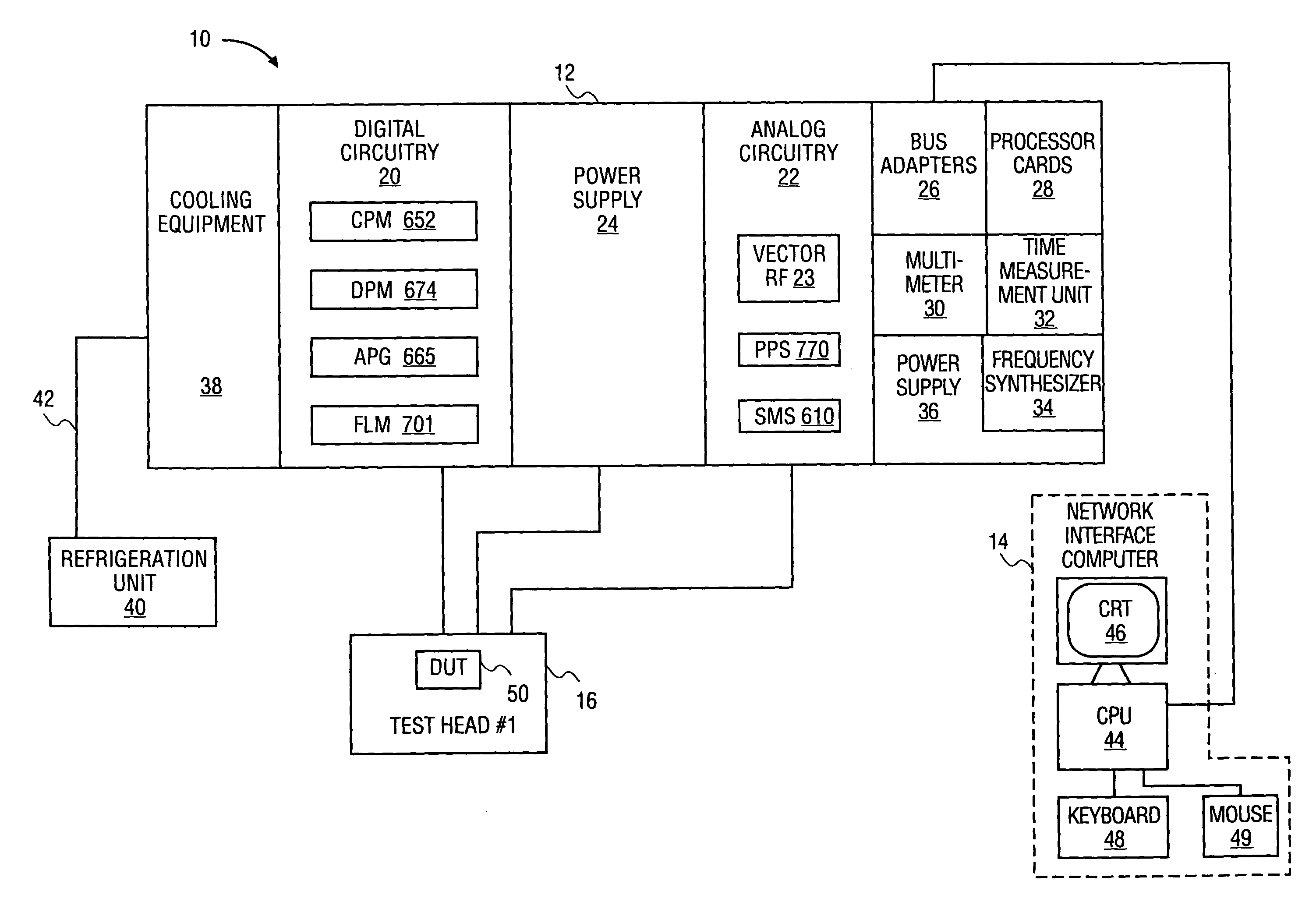
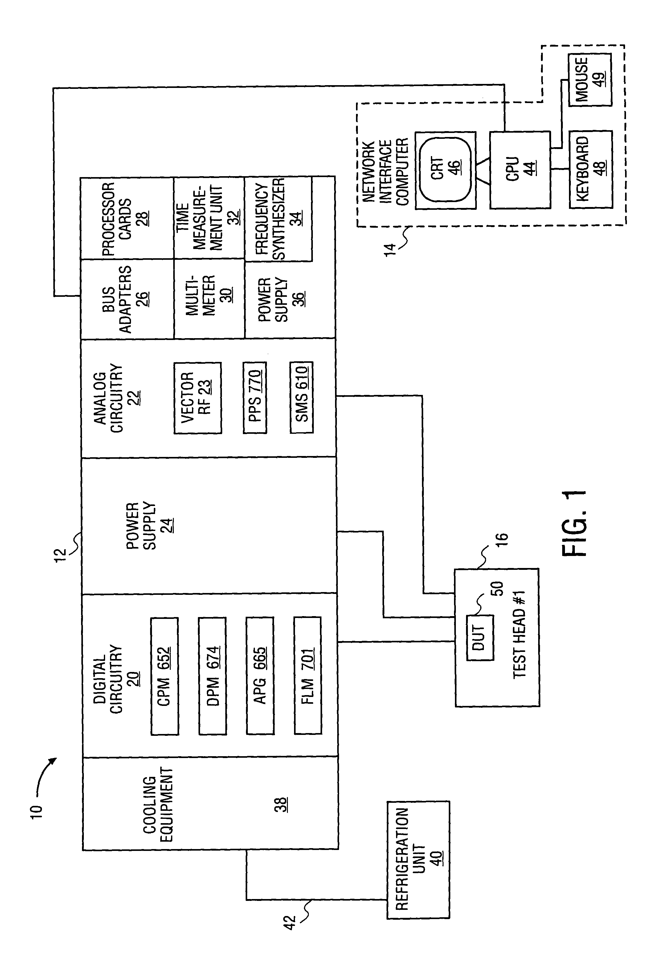
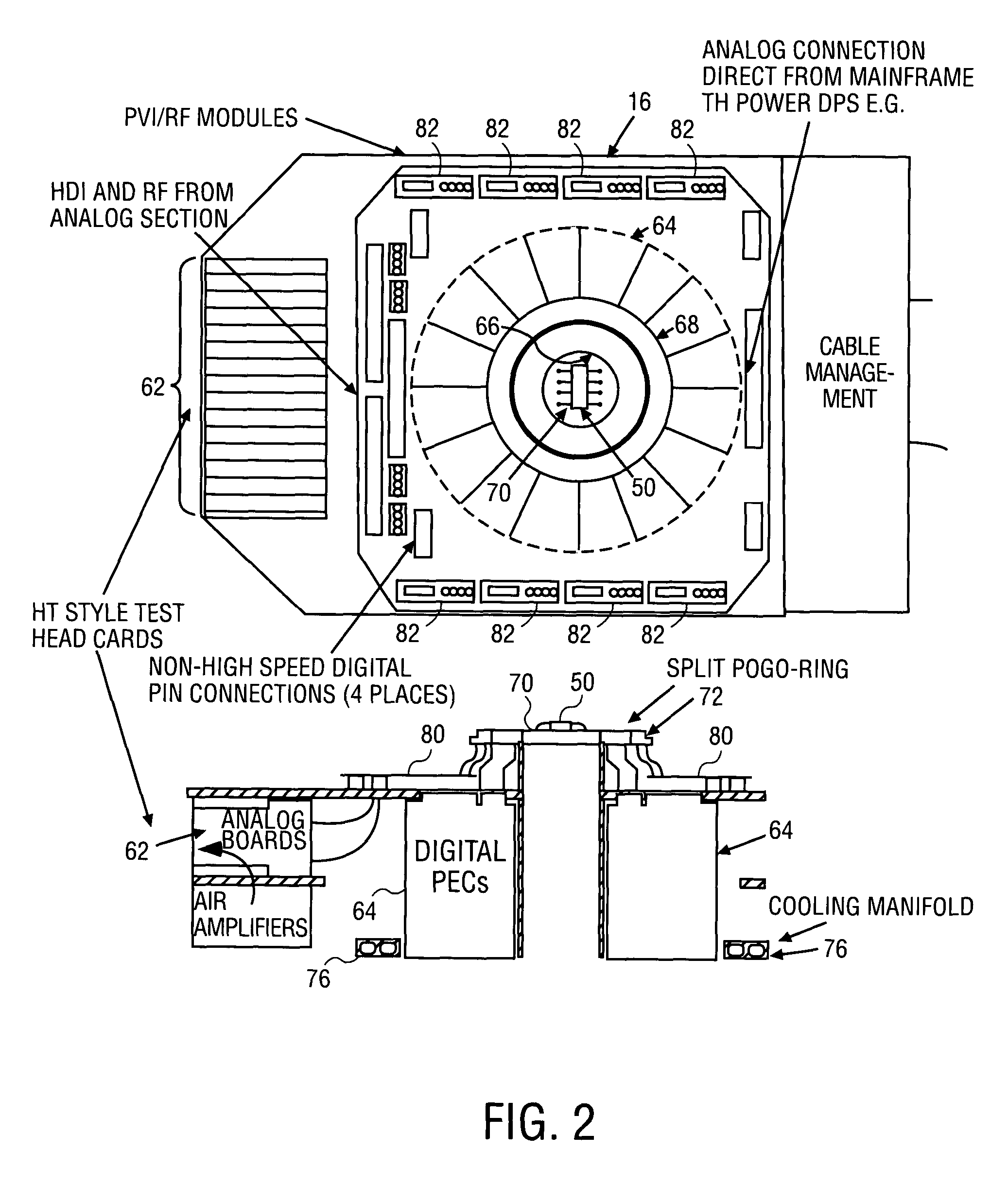
[0044]A single platform electronic tester is described that can test digital integrated circuits, analog integrated circuits, mixed signal integrated circuits, and system-on-a-chip integrated circuits. Various aspects of the single platform electronic tester are described in more detail below. A computer of the tester causes a tester controller to send action packets to analog test circuitry to execute analog tests of a device under test (“DUT”). The computer also causes the digital test circuitry to execute digital tests of the DUT.

[0045]The electronic tester of one embodiment includes a system of distributed processing, synchronization, and highly interchangeable components. An intended advantage is to provide a highly flexible tester that can be relatively quickly and easily reconfigured to test digital ICs, analog ICs, mixed signal ICs, or system-on-a-chip ICs. An intended advantage of this approach is to scale tester cost and size more exactly to the requirements of the particu...


PUM


Abstract

An electronic tester with digital, and analog, and memory test circuitry on a single platform. A test head is coupled to a device under test. The device under test can be a system-on-a-chip integrated circuit, a mixed signal integrated circuit, a digital integrated circuit, or an analog integrated circuit. Digital test circuitry applies digital test signals to the device under test coupled to the test head and receives digital outputs from the device under test in response to the digital test signals. Analog test circuitry applies analog test signals to the device under test coupled to the test head and receives analog outputs from the device under test in response to the analog test signals. Memory test circuitry applies memory test patterns to the device under test coupled to the test head and receives memory outputs from the device under test in response to the memory test patterns. A tester computer supervises the application of digital, analog, and memory test signals from the digital, analog, and memory test circuitry to the device under test such that signals applied to the device under test can be solely digital test signals, solely analog test signals, solely memory test signals, or mixed digital, analog, and memory test signals. The test head, the digital test circuitry, the analog test circuitry, the memory test circuitry, and the computer are operable as a single platform.

Description

[0001]The present application is a divisional of U.S. patent application Ser. No. 09 / 935,453, filed Aug. 22, 2001, now U.S. Pat. No. 6,675,339, which is a divisional of U.S. patent application Ser. No. 09 / 183,038, filed Oct. 30, 1998, which issued as U.S. Pat. No. 6,449,741 B1 on Sep. 10, 2002. The present application claims priority from both applications.[0002]A portion of the disclosure of this patent document contains material that is subject to copyright protection. The copyright owner has no objection to the facsimile reproduction by anyone of the patent disclosure as it appears in the U.S. Patent and Trademark Office patent files or records, but otherwise reserves all copyright rights whatsoever.FIELD OF THE INVENTION[0003]The present invention pertains to the field of electronic test equipment for testing integrated circuits. More particularly, the present invention relates to a single platform electronic tester that includes both digital, analog, and memory test circuitry f...

Claims


Application Information

Patent Timeline
IPC IPC(8): G06F1/06
CPCG01R31/31903G11C29/56G11C2029/5602
Inventor LANIER, KENNETH J.BLETHEN, ROGER W.KELLY, H. NEILDAVIS, MICHAEL G.PERKINS, JEFFREY H.BERRY, TOMMIEBURLISON, PHILLIPDEOME, MARKHANNAFORD, CHRISTOPHER J.TERRENZI, EDWARD J.MENIS, DAVIDCURRY, DAVID W.ROSENFELD, ERIC
Owner LTX CORP
Learn More