
Sequential heart valve leaflet repair device and method of use

a heart valve and leaflet technology, applied in the field of sequential heart valve leaflet repair devices and methods of use, can solve the problems of stenosis and/or insufficiency, valves that cannot close properly, substantial patient discomfort, etc., and achieve the effect of stabilizing at least one heart valve leafl

Inactive Publication Date: 2006-08-22
EDWARDS LIFESCIENCES CORP
View PDF84 Cites 141 Cited by
  • Summary
  • Abstract
  • Description
  • Claims
  • Application Information

AI Technical Summary

Benefits of technology

The device enables effective stabilization and precise fastening of heart valve leaflets, reducing trauma to the patient and improving the accuracy of leaflet coaptation, thereby enhancing the repair process and minimizing residual regurgitation issues post-surgery.

Problems solved by technology

One common form of heart disease involves the deterioration or degradation of the heart valves which leads to stenosis and / or insufficiency.
Insufficiency is a condition in which the valve does not close properly.
For example, the highly invasive nature of the implantation procedure typically results in substantial patient discomfort and requires patients to remain hospitalized for extended recovery periods.
However, the operational lifetimes of tissue valves are typically shorter than mechanical valves and thus may require a subsequent replacement(s) during the patient's lifetime.
Although such annuloplasty procedures have become popular and well accepted, reshaping the surrounding annulus and traditional leaflet repairs do not always lead to optimum leaflet coaptation.
As a result, some patients may still experience residual mitral valve regurgitation following such annuloplasty procedures.
Mehmet Oz is very skill-intensive.
Often, use of these devices results in the less than optimal leaflet stabilization and fastener placement.
Many of these problems arise from the fact that the surgeon is required to capture, retain and fasten the leaflets in one relatively inflexible procedure.
These difficulties are compounded when the leaflets are small or calcified making them difficult to pull together, and in beating heart procedures in which the leaflets are actively functioning throughout the surgery.

Method used


Image

  • Sequential heart valve leaflet repair device and method of use
  • Sequential heart valve leaflet repair device and method of use
  • Sequential heart valve leaflet repair device and method of use

Examples


Embodiment Construction

[0049]Disclosed herein is a description of various illustrated embodiments of the present invention. This description is not to be taken in a limiting sense, but is made merely for the purpose of illustrating the general principles of the invention. The section titles and overall organization of the present description are for the purpose of convenience only and do not limit the present invention.

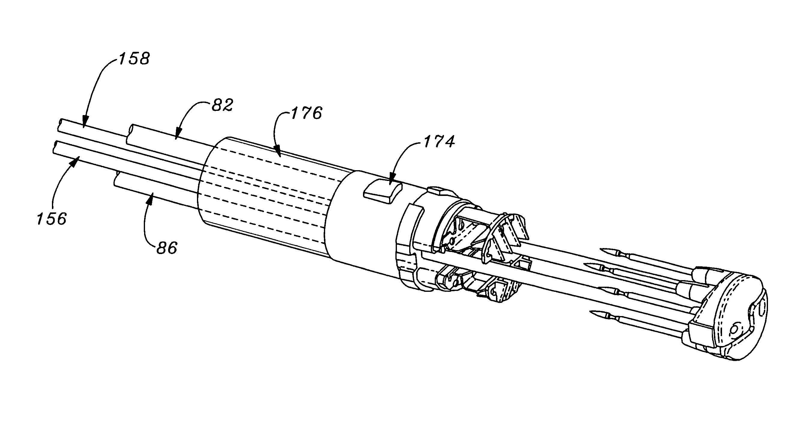
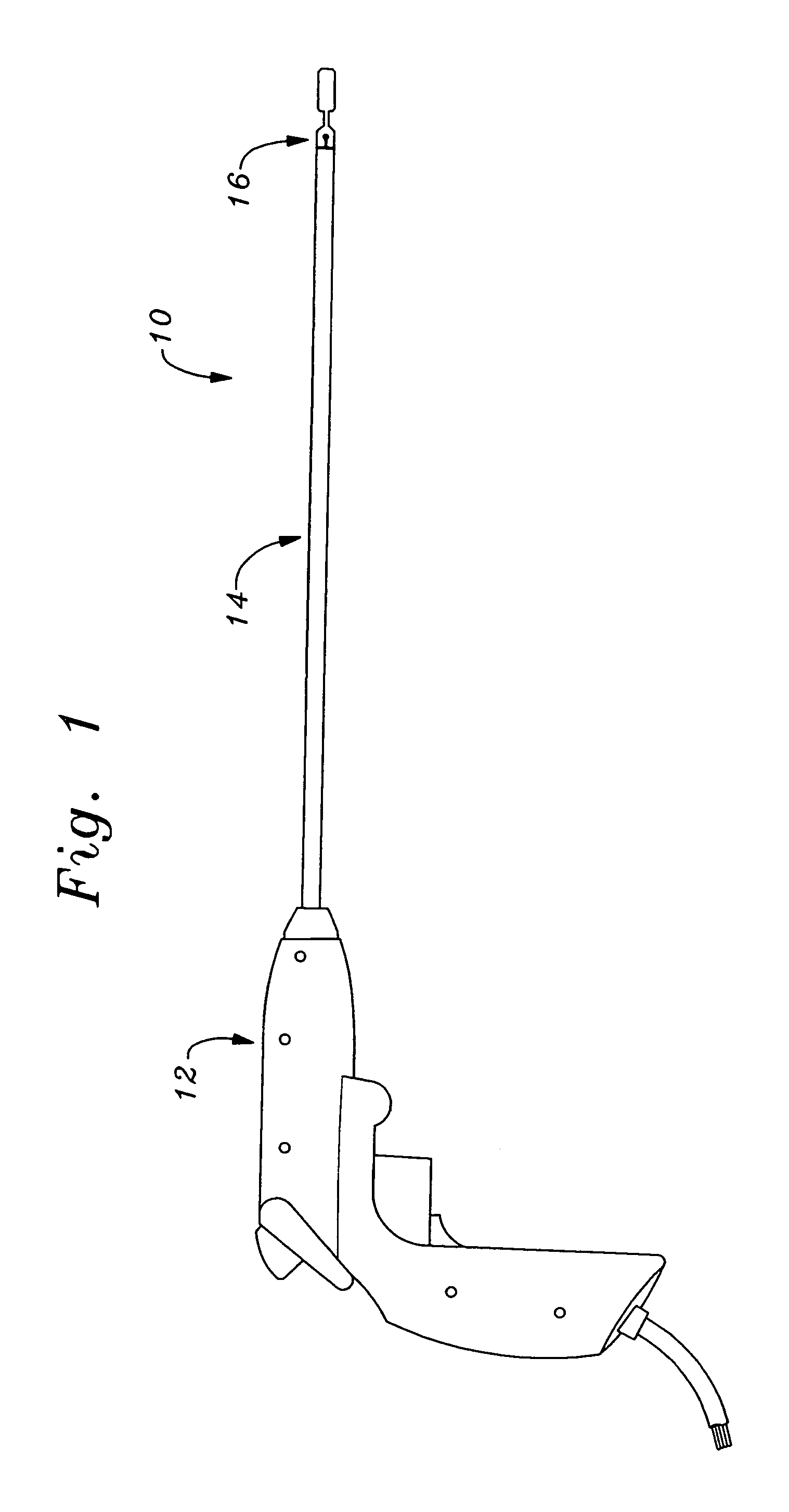
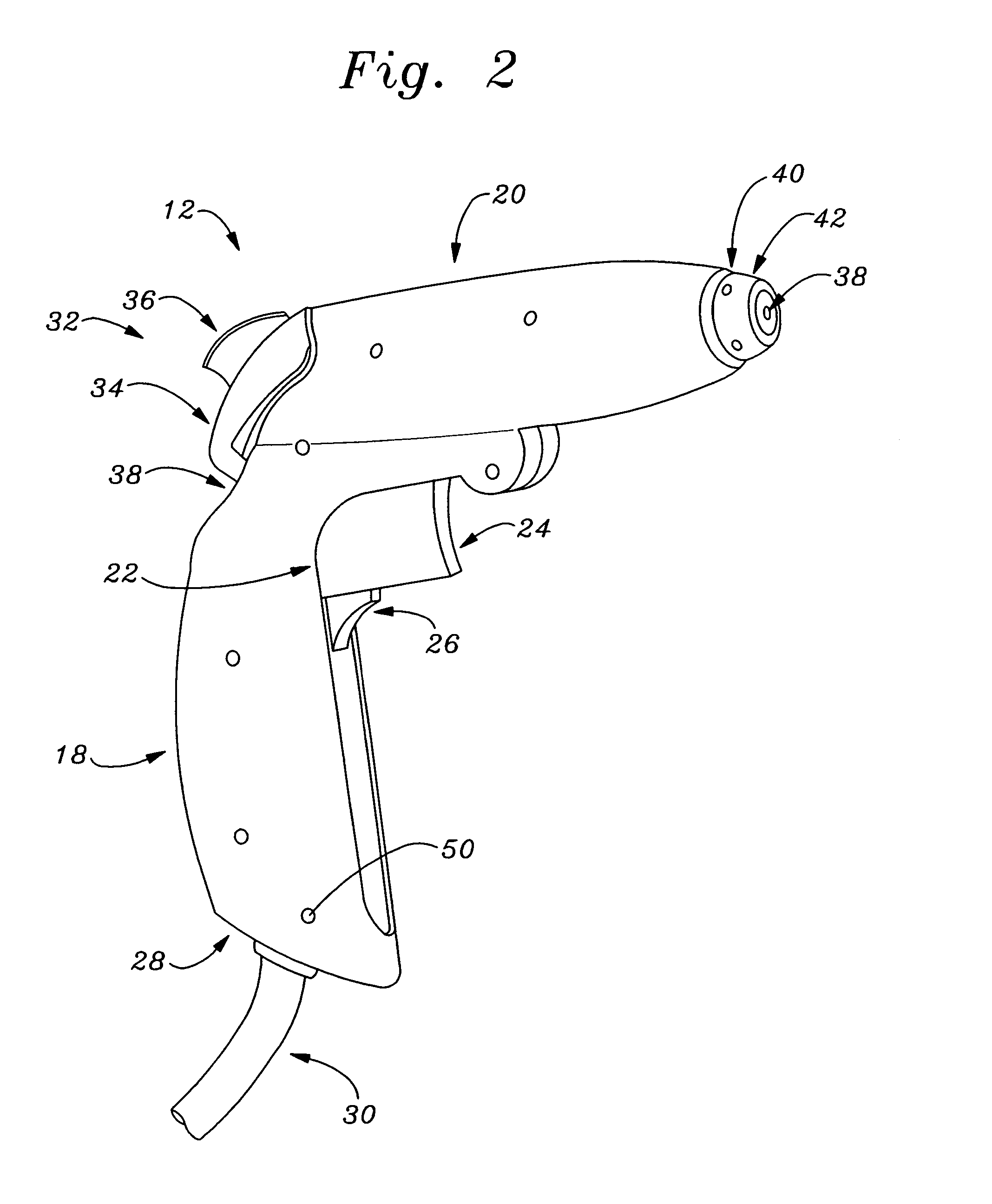
[0050]The methods and devices of the present invention were primarily designed for use in the surgical treatment of heart valves. As those skilled in the art will appreciate, the exemplary sequential repair device disclosed herein is designed to minimize trauma to the patient before, during, and subsequent to a surgical procedure, while providing improved heart valve leaflet stabilization and enhanced placement of a fastening device thereon. The repair device of the present invention is particularly useful in repairing dysfunctional mitral valves by stabilizing the discrete valvular tissue ...


PUM


Abstract

A heart valve and tissue repair device for independently, selectively and sequentially grasping heart valve leaflets and independently, selectively and sequentially applying one or more fasteners thereto is disclosed. The device includes a leaflet engaging tip having one or more graspers capable of individually and sequentially grasping leaflets, and one or more deployable fasteners capable of fastening the leaflets. An actuation system for the device individually and selectively controls the graspers and deploys the one or more fasteners. Vacuum pressure from an external vacuum source can be used to grasp the leaflets via a selector system that controls the actuation system so as to individually and sequentially apply vacuum force to the graspers.

Description

CROSS REFERENCE TO RELATED APPLICATIONS[0001]This application discloses subject matter related to co-pending U.S. patent application Ser. No. 09 / 562,406, filed May 1, 2000, now U.S. Pat. No. 6,626,930, entitled “Minimally Invasive Mitral Valve Repair Method And Apparatus”, and U.S. patent application Ser. No. 09 / 778,392, filed Feb. 6, 2001, now abandoned, entitled “Method and System for Tissue Repair Using Dual Catheters”. The entire disclosures of the aforementioned United States patent applications are incorporated herein by reference.BACKGROUND OF THE INVENTION[0002]In vertebrate animals, the heart is a hollow muscular organ having four pumping chambers: the left atrium, the left ventricle, the right atrium and the right ventricle. The atria are isolated from their respective ventricles by one-way valves located at the respective atrial-ventricular junctions. These valves are identified as the mitral (or bicuspid) valve on the left side of the heart, and tricuspid valve on the ri...

Claims


Application Information

Patent Timeline
Patent Type & Authority Patents(United States)
IPC IPC(8): A61B17/04A61F2/48A61B17/00A61F2/24
CPCA61B17/00234A61B17/0469A61F2/2409A61B2017/0472A61B2017/00783
Inventor SCHRECK, STEFAN
Owner EDWARDS LIFESCIENCES CORP
Learn More