
Device for parallel and synchronous injection for sequential injection of different reagents

a technology of synchronous injection and reagent injection, which is applied in the direction of mixers, chemical libraries, combinational chemistry, etc., can solve the problems of difficult control of parallel series synchronization and the inability of prior-art techniques to achieve the same

Inactive Publication Date: 2006-08-22
COMMISSARIAT A LENERGIE ATOMIQUE ET AUX ENERGIES ALTERNATIVES
View PDF8 Cites 66 Cited by
  • Summary
  • Abstract
  • Description
  • Claims
  • Application Information

AI Technical Summary

Benefits of technology

Enables precise and synchronized injection of reaction series with volumes less than 1 μl across multiple channels, maintaining synchronization and minimizing desynchronization issues, while allowing for flexible operation modes suitable for various biological and chemical procedures.

Problems solved by technology

One of the technical problems in realizing micro-systems based on the principle of FIA concerns the large number of micro-channels and the design of the automated apparatuses enabling production of the reaction series.
The prior-art techniques, however, do not enable obtaining the same result using reaction volumes that are very small (less than a μl) and over a plurality of parallel channels with the same reactant having to be injected simultaneously over all of the channels.
Thus, in practice, it is very difficult to control synchronization of parallel series.

Method used


Image

  • Device for parallel and synchronous injection for sequential injection of different reagents
  • Device for parallel and synchronous injection for sequential injection of different reagents
  • Device for parallel and synchronous injection for sequential injection of different reagents

Examples


Embodiment Construction

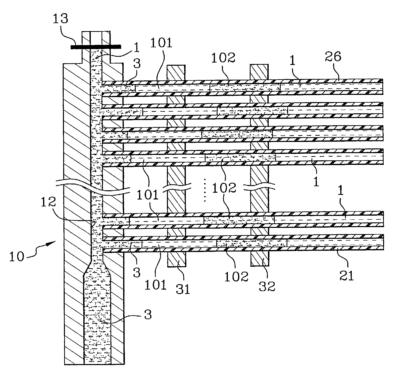
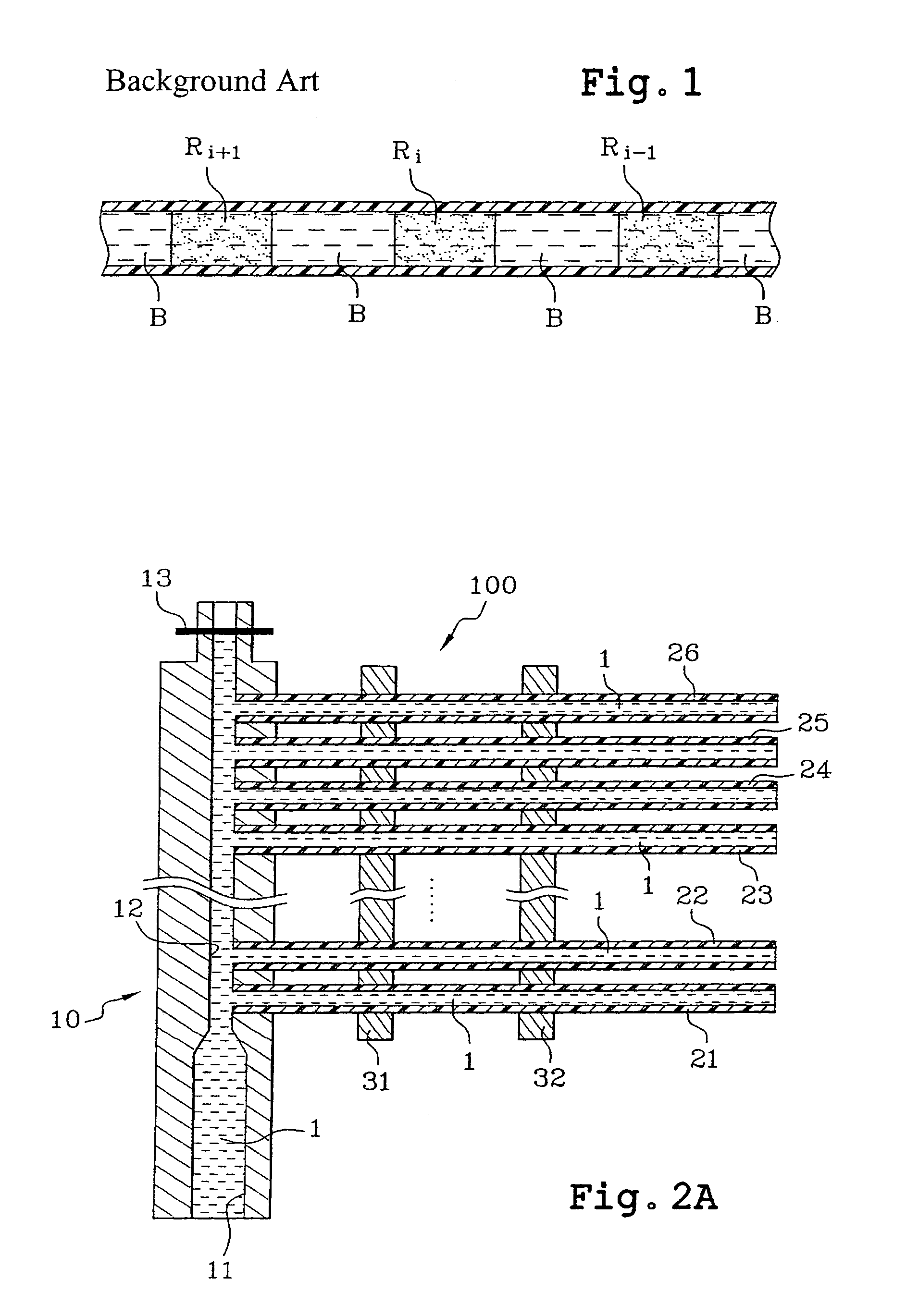
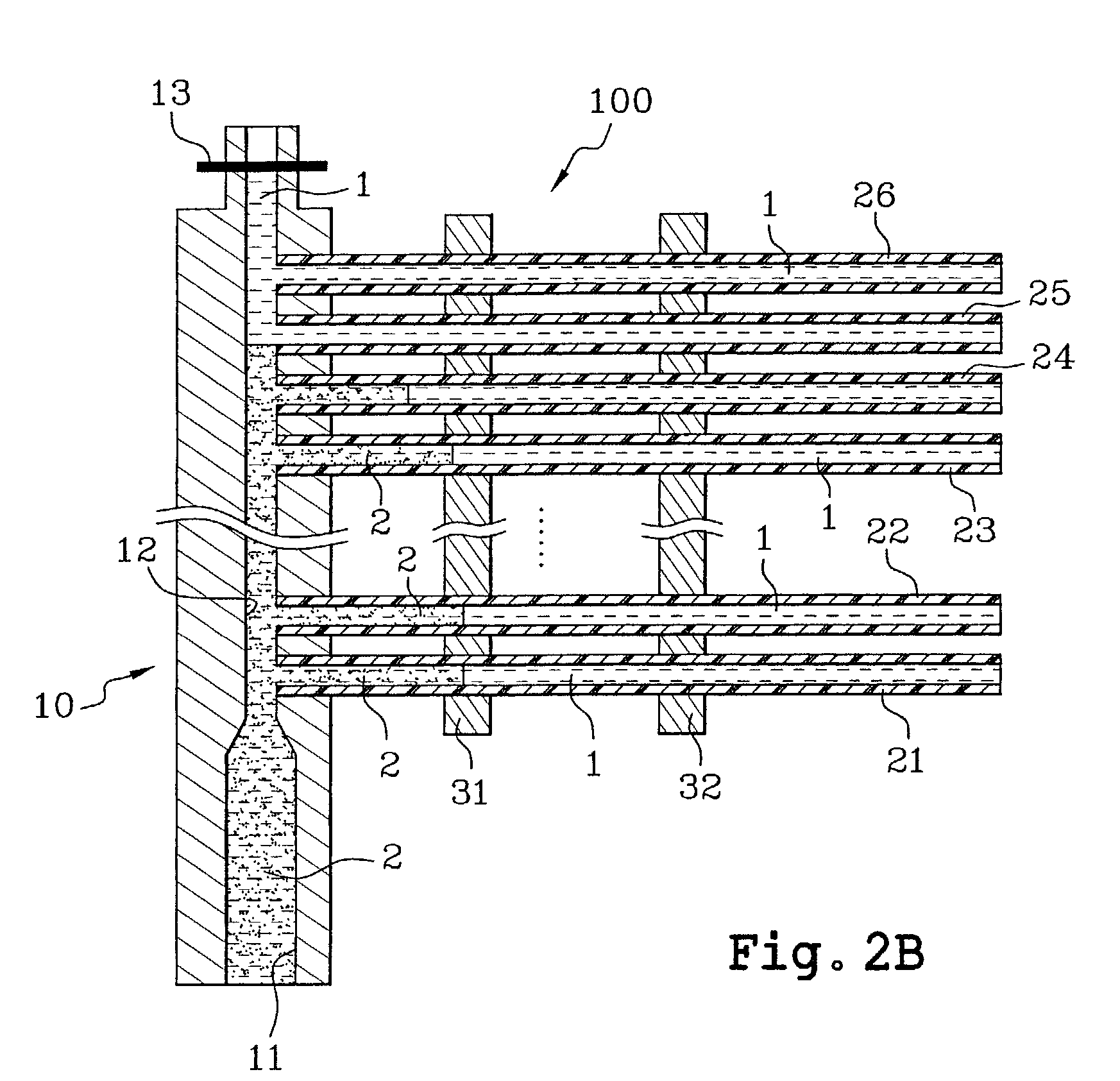
[0040]FIGS. 2A to 2G are sectional views of the parallel and synchronized injecting device according to the invention.

[0041]The injecting device is comprised of an elongated part 10 perforated along its longitudinal axis by a traversing hole forming an injection chamber and comprising a channel input 11 extended by an injection channel 12. The part 10 also comprises holes in the axis perpendicular to the axis of the injection channel 12 and leading into the injection channel 12. These holes are used for accommodating the first ends of micro-capillaries 21 to 26 or micro-channels. The micro-capillaries are formed, for example, using molten silicon and are lined with polyimide of the type described in international application WO-A-00 / 30751, for example. They can be of very small diameter, typically several μm to several hundreds of μm. They can be fixed to the part 10 by gluing.

[0042]The second ends of the micro-capillaries can be formed by a micro-system (not shown).

[0043]The input ...


PUM

PropertyMeasurementUnit
temperature T2aaaaaaaaaa
volumesaaaaaaaaaa
physico-chemical propertyaaaaaaaaaa

Abstract

The invention relates to a microfluidic device for injecting series of mobile reaction chambers (102, 103) having non-miscible segmenters (101) in micro-channels (21 to 26), comprising:injection means (10) for injecting into microreaction channels alternatingly and in parallel liquid to form mobile reaction chambers and liquid for forming the segmenters;means for controlling the progression of one of the two liquids, applied to act on one zone (31) of each microchannel delimiting an injection volume of said liquid; the control means being able to cause stopping or slowing of the progression of said liquid over the zone of each microchannel by exerting an action based on a physico-chemical property of the liquid and said action not affecting the other liquid.

Description

TECHNICAL FIELD[0001]The invention relates to a device for parallel and synchronous injection for sequentially injecting different reagents. It also relates to a biological reactor and a method for implementing a biological, biochemical or chemical procedure using the samples.[0002]In a general fashion, the invention is applicable to all filed requiring high through-put or HTS chemical or biological analysis (i.e., “high through-put screening”).DESCRIPTION OF THE PRIOR ART[0003]One of the principles taken from microfluidic technology for biological or chemical applications is the possibility of miniaturizing, parallelizing and serializing reactions. This is, for example, very important for genomic assays requiring automated apparatuses enabling study of a large number of genes while using minimal volumes and assay time. The same applies to proteomic assays.[0004]Miniaturization was made possible by developments in silicon, glass, or plastic microtechnologies. There is an extensive l...

Claims


Application Information

Patent Timeline
Patent Type & Authority Patents(United States)
IPC IPC(8): B01L3/00B01F13/00B01F15/00B01J19/00C40B60/14G01N35/00G01N35/08
CPCB01F13/0071B01F13/0077B01F15/00344B01J19/0093B01L3/563G01N35/08B01F13/0076G01N2035/00237B01F15/00123B01J2219/00286B01J2219/00306B01J2219/00353B01J2219/00389B01J2219/00414B01J2219/00418B01J2219/00495B01J2219/00585B01J2219/0059B01J2219/00657B01J2219/00659B01J2219/0068B01J2219/00783B01J2219/00873B01J2219/00891B01J2219/0093B01L2200/027B01L2200/0605B01L2300/1822B01L2400/0403B01L2400/0475B01L2400/06B01L2400/082C40B60/14Y10T137/0391B01F33/3032B01F33/3031B01F33/3021B01F35/20B01F35/2211
Inventor FOUILLET, YVESSARRUT, NICOLASGRUSS, ANTOINE
Owner COMMISSARIAT A LENERGIE ATOMIQUE ET AUX ENERGIES ALTERNATIVES
Learn More