Method for cooling electronic components and thermally conductive sheet for use therewith

a technology of electronic components and thermally conductive sheets, which is applied in the direction of cooling/ventilation/heating modifications, thin material processing, semiconductor devices, etc., can solve the problems of increasing electric power consumption and heat generation, generating significant amounts of heat for high-performance electronic components, and urgent cooling of electronic components. achieve the effect of efficient operation

Inactive Publication Date: 2006-08-22
POLYMATECH CO LTD
View PDF7 Cites 77 Cited by
  • Summary
  • Abstract
  • Description
  • Claims
  • Application Information

AI Technical Summary

Benefits of technology

[0010]To that end, it is an objective of the present invention to provide a method for cooling electronic components, by which the generated heat is efficiently conducted to a cooling member while terminals of the electronic components and electric circuits around them remain electrically insulated. It is also an objective of the present invention to provide a thermally conductive sheet for use with the electronic components.

Problems solved by technology

As the performance of electronic components, such as CPUs, integrated in electronic instruments improves, the amounts of electric power consumption and heat generation have increased significantly.
Consequently, cooling these electronic components has become an urgent problem that must be addressed in order to maintain the performances of the electronic components.
However, recently developed high-performance electronic components generate significant amounts of heat.
The conventional thermally conductive sheets that contain thermally conductive fillers having a high electrical resistance, such as alumina and magnesia, fail to provide a sufficiently high heat conductivity, in particular a heat conductivity of 6 W / m·K or more, to effectively conduct the heat generated by the high-performance electronic components to a cooling member.
This type of thermally conductive sheet, however, has a low electrical resistance and may allow an undesirable electrical conduction near terminals and electronic circuits of the electronic components.
As a result, such a thermally conductive sheet has a limited range of applications.

Method used


Image

  • Method for cooling electronic components and thermally conductive sheet for use therewith
  • Method for cooling electronic components and thermally conductive sheet for use therewith
  • Method for cooling electronic components and thermally conductive sheet for use therewith

Examples


example 1

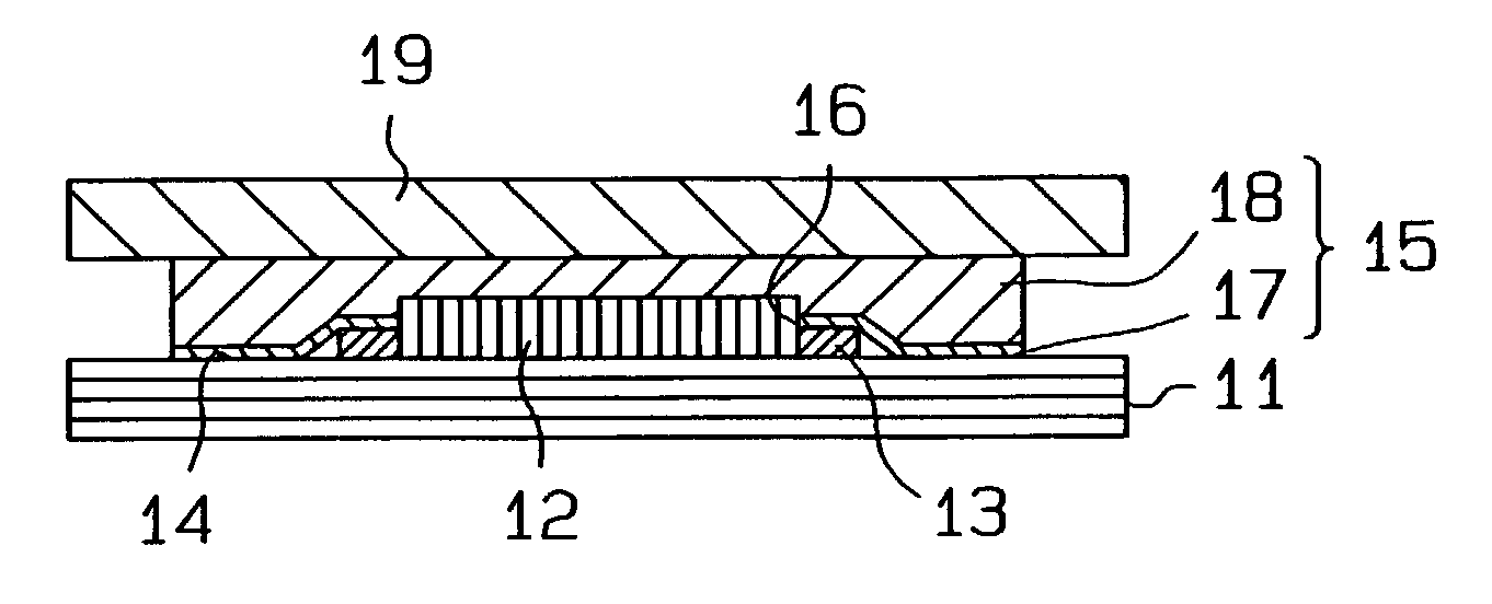
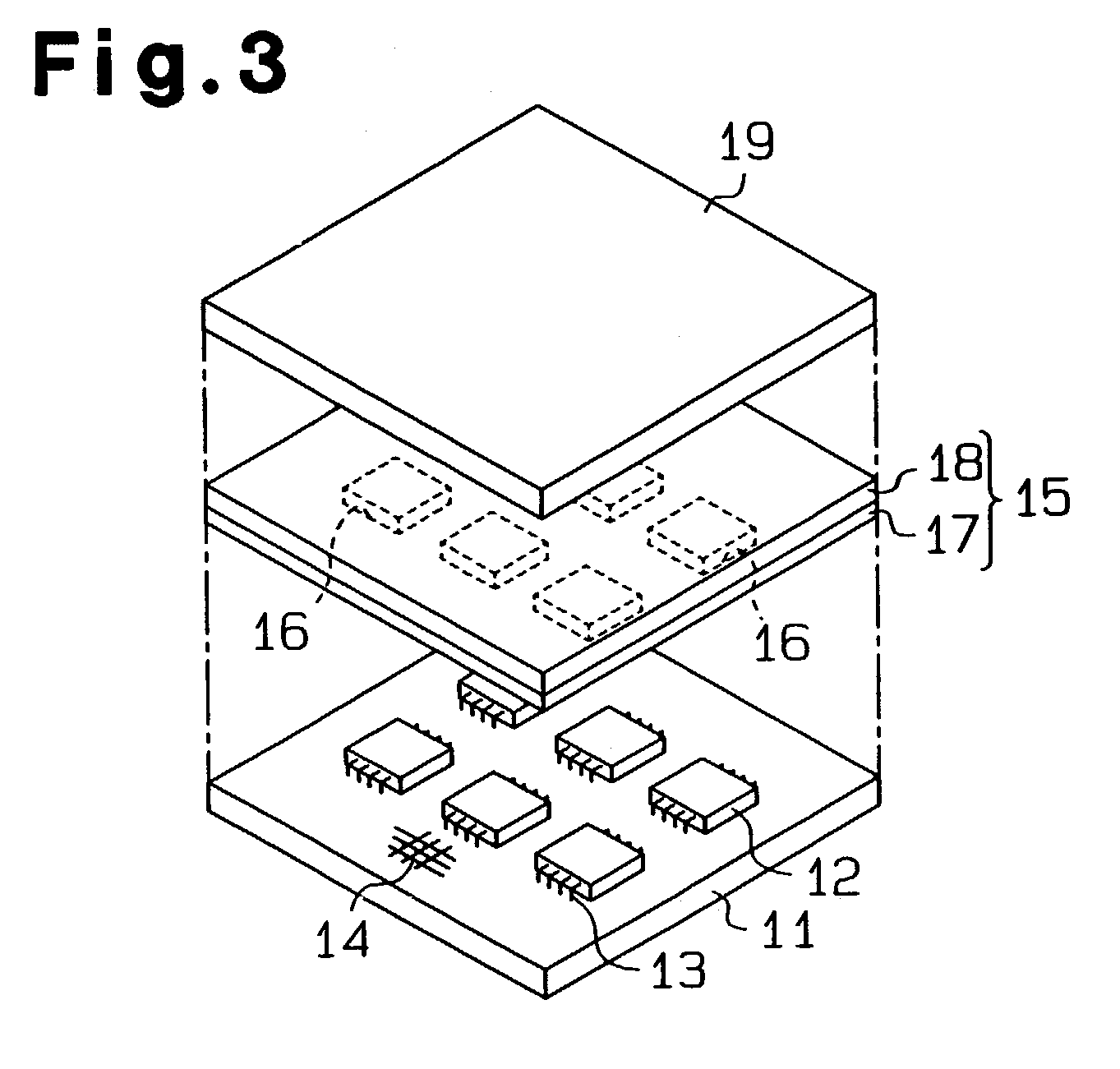
[0048]60% by volume of an addition reaction type liquid silicone gel (WACKER ASAHI KASEI SILICONE Co., Ltd.) having a specific gravity of 1.0 as the matrix was mixed with 20% by volume of graphitized carbon fiber having an average fiber length of 15 μm and 20% by volume of an alumina powder having an average particle size of 2 μm, each serving as the thermally conductive filler. The mixture was mixed in a mixer until the mixture was uniform and the uniform mixture was deaerated in vacuum. The mixture was then filled into a hollow aluminum die having a sheet-shaped cavity with 0.5 mm clearance and coated with a fluorine resin (polytetrafluoroethylene), and the mixture in the die was heat-cured in a magnetic field directed across the clearance of the cavity (i.e. along the thickness of a layer to be formed) to obtain a thermally conductive layer 18. The graphitized carbon contained in the resultant thermally conductive layer 18 was oriented along the thickness of the thermally conduct...

example 2

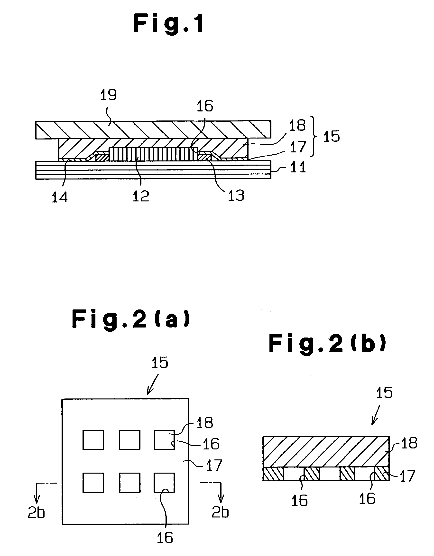
[0050]A 0.5 mm thick thermally conductive layer 18 was formed in the same manner as in Example 1. As shown in FIG. 2(b), the parts of the thermally conductive layer 18 corresponding to the electronic components 12 were masked in conventional manner. Using the screen printing technique, a silicone ink having an electrical resistance of 1.0×10¹² Ω·cm or higher was applied over the masked layer to a thickness of 0.01 mm and was completely dried to form an insulation layer 17. This completed a thermally conductive sheet 15.

example 3

[0051]A 0.5 mm thick thermally conductive layer 18 was formed in the same manner as in Example 1.

[0052]Then, a polyester film to which a silicone adhesive with an electrical resistance of 1.0×10¹² Ω·cm had been applied to a thickness of 0.2 mm was prepared, and as shown in FIG. 2(a), the areas of the sheet corresponding to the electronic components 12 were cut out from the film to form a plurality of windows 16. The silicone adhesive-coated polyester film was then laminated onto the thermally conductive layer 18 to form an insulation layer 17. This completed a thermally conductive sheet 15.


PUM

PropertyMeasurementUnit
thicknessaaaaaaaaaa
thermal conductivityaaaaaaaaaa
thicknessaaaaaaaaaa

Abstract

A thermally conductive sheet includes a thermally conductive layer and an insulation layer laminated onto the thermally conductive layer. The thermally conductive layer includes matrix containing thermally conductive filler having an electrical conductivity. The insulation layer contains thermally conductive filler having an insulating property. The thermally conductive sheet is disposed so that the insulation layer covers the terminal of the electronic component and the electric circuit. At this time, the thermally conductive layer covers and closely contacts with the insulation layer and the electronic component. The heat generated by the electronic component is conducted to a cooling member through the thermally conductive layer and is ultimately dissipated.

Description

CROSS REFERENCE TO RELATED APPLICATIONS[0001]Pursuant to 35 USC § 119, this application claims the benefit of Japan Patent Application No. 2001-397353 filed Dec. 27, 2001.BACKGROUND OF THE INVENTION[0002]The present invention relates to a method for cooling electronic components used within information instruments, imaging instruments, mobile telecommunication instruments, and other electronic instruments. More particularly, the present invention relates to a method for cooling electronic components by conducting the heat to a cooling member, such as a radiator and a thermally conductive metal plate, and a thermally conductive sheet for use with such a method.[0003]As the performance of electronic components, such as CPUs, integrated in electronic instruments improves, the amounts of electric power consumption and heat generation have increased significantly. Consequently, cooling these electronic components has become an urgent problem that must be addressed in order to maintain th...

Claims


Application Information

Patent Timeline
Patent Type & Authority Patents(United States)
IPC IPC(8): B32B1/04H05K7/20H01L23/36H01L23/373
CPCH01L23/3733H01L2924/0002Y10T428/23H01L2924/00Y10T428/31663H05K7/20
Inventor TAKAHASHI, KOUYA
Owner POLYMATECH CO LTD
Why Eureka
Try Eureka