Remote reagent chemical ionization source

a technology of reagents and reagents, applied in the field of remote reagent chemical ionization sources, can solve the problems of poor sampling efficiency, general approach restrictions, and difficult sampling of ions from atmospheric pressure sources to small cross-sectional targets or through small cross-sectional apertures and tubes (usually less than 1 mm) into mass spectrometers, etc., to achieve the effect of improving the collection efficiency of ions, facilitating efficient sample ionization and collection

Inactive Publication Date: 2006-08-22
CHEM SPACE ASSOCS
View PDF32 Cites 109 Cited by
  • Summary
  • Abstract
  • Description
  • Claims
  • Application Information

AI Technical Summary

Benefits of technology

[0014]A preferred embodiment of the invention is the configuration of a high efficiency ionization source utilizing remote reagent ion generation coupled with a large reaction volume electro-optical well to facilitate efficient sample ionization and collection. The novelty of this device is the manner of isolation of the electric fields in the reagent ion generation region from the electric fields of the reaction or sample ionization region and the product ion-sampling region or funnel region. This is accomplished through the utilization of a perforated and laminated surface that efficiently passes reagent ions from the reagent source region to the reaction region without significant penetration of the fields from the adjacent regions.
[0015]One object of the present invention is to increase the collection efficiency of ions and/or charged particles at a collector, or through an aperture or tube into a vacuum system, by creating a very small cross-sectional area beam of ions and/or charged particles from highly dispersed atmospheric pressure ion sources. The present invention has a significant advantage over prior art in that the use of a Laminated High Transmission Element (L-HTE) to separate reagent ion generation from product ion formation and ion focusing allows precise shaping of fields in both regions. Ions can be generated in large ion source regions without losses to walls. Droplets have longer time to evaporate and/or desorb neutrals or ions without loss from the sampling stream. Source temperatures can be lower because rapid evaporation is not required. This can prevent thermal decomposition of some labile compounds. Counter electrodes for APCI needles do not have to be the plate lens as practices with most conventional sources or even the HTE (high transmission elements, as disclosed in our own U.S. Pat. No. 6,744,041 (2004), U.S. Pat. No. 6,818,889 (2004), U.S. Pat. No. 6,878,930 (2005), and U.S. Pat. No. 6,888,132 (2005); U.S. patent application Ser. Nos. 10/661,842 (2003) al.; and U.S. patent publication 2004/0245458 and World patent publication 2004/110583); or our high transmission laminated tube as disclosed in our U.S. patent application Ser. No. 10/688,021 (2003)). The aerosol and plasma can be generated remotely and ions ca

Problems solved by technology

As a consequence of a wide variety of dispersive processes, efficient sampling of ions from atmospheric pressure sources to small cross-sectional targets or through small cross-sectional apertures and tubes (usually less than 1 mm) into a mass spectrometer becomes quite problematic.
This general approach in severely restricted by the need for precise aperture alignment and source positioning, for example, in the case of an APCI source the position of the discharge needle; and very poor sampling efficiencies.
The use of this low field photo-ionization source has lead to some improvement in sampling efficiency from atmospheric pressure sources, but these sources also suffer from a lower concentration of reagent ions when compared to traditional APCI sources.
This approach to focusing ions from atmospheric sources is limited by the acceptance angle of the electrostatic fields generated at the cone.
As with planar apertures, source positioning relative to the aperture is also critical to performance; and collection efficiency is quite low.
But this configuration has a clear disadvantage in tha

Method used


Image

  • Remote reagent chemical ionization source
  • Remote reagent chemical ionization source
  • Remote reagent chemical ionization source

Examples


Embodiment Construction

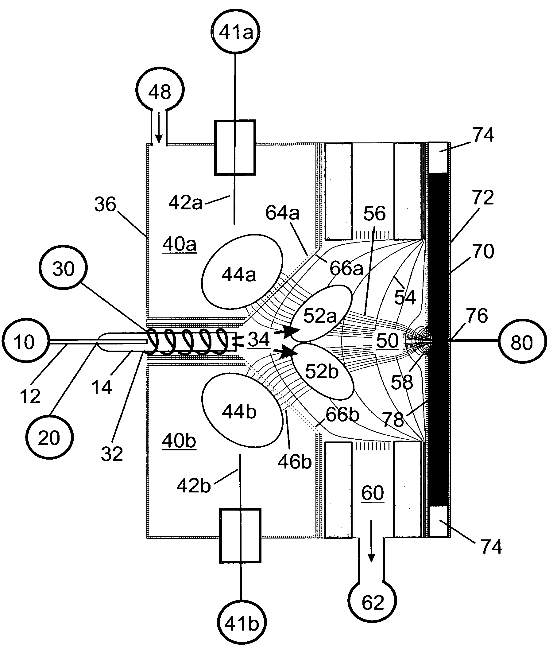
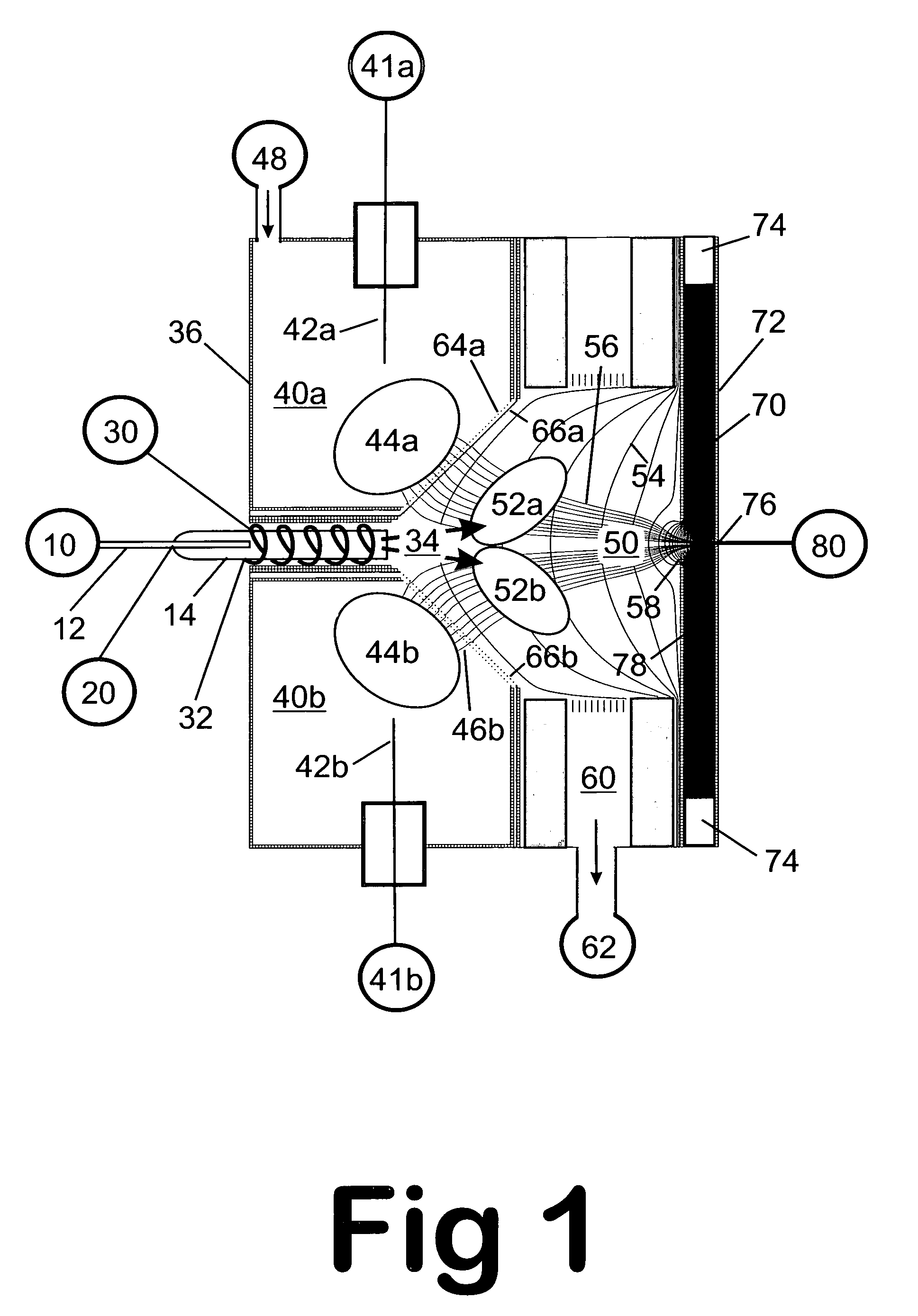
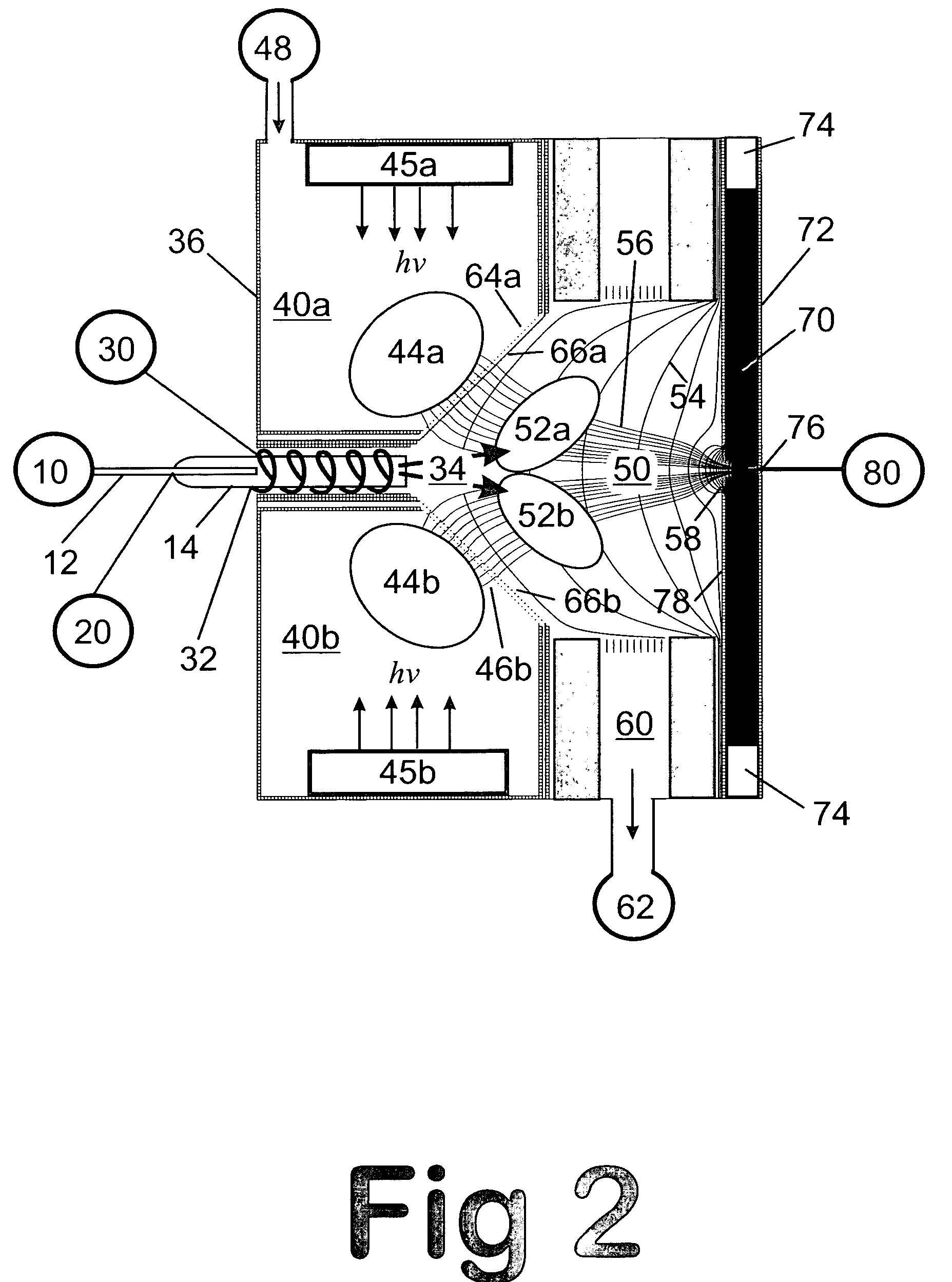
—FIG. 1 (Remote Atmospheric Pressure Chemical Ionization, Remote-APCI)

[0060]A preferred embodiment of the chemical ionization source of the present invention at atmospheric pressure is illustrated in FIG. 1. Sample from a sample source 10 is delivered to a nebulizer 14 by a sample delivery means 12 through an ion source entrance wall 36. This embodiment contains a heated nebulizer for nebulization and evaporation of sample streams emanating from liquid chromatographs and other liquid sample introduction devices. The liquid sample is heated, nebulized, and vaporized by the input of nebulization gas from a nebulization gas source 20 and by heat from heating coils 32 generated from a nebulizer heating supply 30. The nebulizer generates a sample aerosol flow 34 with the sample being vaporized into the gas-phase and proceeding into a reaction or sample ionization region 52.

[0061]Reagent ions are generated in a reagent ion generation region 40 by electron ionization from a discharge needl...


PUM


Abstract

An improved ion source and portable analyzer for collecting and focusing dispersed gas-phase ions from a reagent source at atmospheric or intermediate pressure, having a remote source of reagent ions generated by direct or alternating currents, separated from a low-field sample ionization region by a stratified array of elements, each element populated with a plurality of openings, wherein DC potentials are applied to each element necessary for transferring reagent ions from the remote source into the low-field sample ionization region where the reagent ions react with neutral and/or ionic sample forming ionic species. The resulting ionic species are then introduced into the vacuum system of a mass spectrometer or ion mobility spectrometer. Embodiments of this invention are methods and devices for improving sensitivity of mass spectrometry when gas and liquid chromatographic separation techniques or probes containing samples are coupled to atmospheric and intermediate pressure photo-ionization, chemical ionization, and thermospray ionization sources.

Description

CROSS-REFERENCE TO RELATED APPLICATIONS[0001]This is a continuation of application Ser. No. 10 / 449,344, filed 2003 May 30, now U.S. Pat. No. 6,888,132, granted May 3, 2005. This application is related to application Ser. No. 08 / 946,290, filed Oct. 7, 1997, now U.S. Pat. No. 6,147,345, granted Nov. 14, 2000; application Ser. No. 09 / 877,167, filed Jun. 8, 2001, now U.S. Pat. No. 6,744,041, granted Jun. 1, 2004; application Ser. No. 10 / 449,147, filed May 31, 2003, now U.S. Pat. No. 6,818,889, granted Nov. 16, 2004; application Ser. No. 10 / 785,441, filed Feb. 23, 2004, now U.S. Pat. No. 6,878,930, granted Apr. 12, 2005; application Ser. No. 10 / 661,842, filed Sep. 12, 2003, application Ser. No. 10 / 688,021, filed Oct. 17, 2003, application Ser. No. 10 / 863,130, filed Jun. 7, 2004, now patent application publication No. 2004 / 0245458, published Dec. 9, 2004; and application Ser. No. 10 / 862,304, filed Jun. 7, 2004, now patent application publication No. 2005 / 0056776, published Mar. 27, 2005.G...

Claims


Application Information

Patent Timeline
IPC IPC(8): H01J49/00
CPCH01J49/0468H01J49/145H01J49/067
Inventor SHEEHAN, EDWARD WWILLOUGHBY, ROSS C
Owner CHEM SPACE ASSOCS
Why Eureka
Try Eureka