Programmable multifunction electronic camera

a multi-functional, electronic camera technology, applied in the field of programmable multi-functional electronic cameras, can solve the problems of inability to meet the needs of specific applications, and inability to manufacture custom-designed detector element image sensors required by these cameras in small quantities for specific applications, and achieve the effect of small size and compactness

Inactive Publication Date: 2006-08-22
ZEROCONZERO LLC +1
View PDF5 Cites 41 Cited by
  • Summary
  • Abstract
  • Description
  • Claims
  • Application Information

AI Technical Summary

Benefits of technology

[0017]Accordingly, one object of the present invention is to provide a special purpose electro

Problems solved by technology

Prior art special purpose cameras currently have a number of disadvantages that make them undesirable in many applications.
First, the custom designed detector element image sensors required by these cameras are generally manufactured in small quantities for specific applications and tend to be expensive.
This causes these types of cameras to be expensive.
Second, these cameras tend to be large and bulky because the custom designed detector element image sensors usually require amplifiers for each detector element that are physically separated from the detector elements and connected using separate cables.
This camera, however, still required separate cables for each ring and wedge shaped detector element in the image sensor.
Special purpose electronic cameras have limited capabilities because they include custom designed detector element image sensors that can only be used to perform certain specific functions.
Image sensors including ring shaped detector elements cannot be used to perform the same functions that are performed by image sensors including wedge shaped detector elements.
While hybrid detector element image sensors can be used to increase the capabilities of special purpose cameras, they may not be practical in some applications.
For example, hybrid image sensors may be too expensive or too large to be used in a given application.
Furthermore, even where hybrid image sensors can be used, special purpose cameras are still limited to performing only the functions that can be performed using the hybrid image sensor.
First, it is inherently expensive because it is a special purpose image sensor and has limited application.
Second, although both sub arrays are present on a single detector chip, only one sub array can be used at any given time.
Third, each detector element requires a dual-stage amplifier, which doubles the number of amplifiers required by this image sensor and increases the size of the circuit board required to support the image sens

Method used


Image

  • Programmable multifunction electronic camera
  • Programmable multifunction electronic camera
  • Programmable multifunction electronic camera

Examples


Embodiment Construction

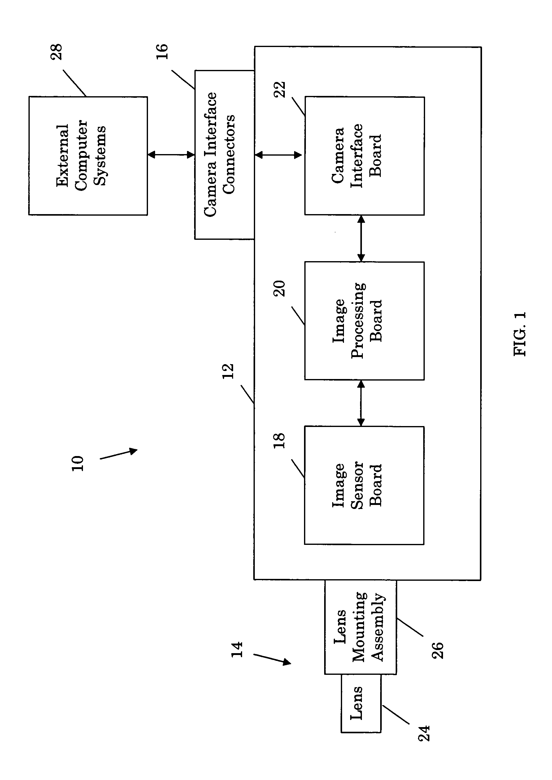
[0039]Referring to FIG. 1, one embodiment of the programmable multifunction electronic camera 10, of the present invention includes an enclosure 12, a lens assembly 14 (also referred to as a light collecting assembly), camera interface connectors 16, an image sensor board 18, an image processing board 20 (or simply a processing board), and a camera interface board 22. The lens assembly 14 and camera interface connectors 16 are mounted on the enclosure 12 and the image sensor, image processing, and camera interface boards 18, 20 and 22 are mounted adjacent to one another inside the enclosure 12. The image sensor board 18 is mounted adjacent to the lens assembly 14 so that the lens assembly 14 can focus images on an image sensor included with the image sensor board 18 and discussed in more detail below. The camera interface board 22 is mounted adjacent to and is connected to the camera interface connectors 16. The image sensor board 18 is connected to the image processing board 20. Th...


PUM


Abstract

A programmable multifunction electronic camera uses a commercial pixel digital energy sensor to generate detector element signal digital data normally generated by expensive, custom designed, detector element energy sensors. The camera performs this function by retrieving pixel signal digital data and pixel location data from the pixel energy sensor, retrieving detector element energy sensor masks containing information regarding the size, shape, and location of detector elements included in the detector element energy sensors, mapping the pixels included in the pixel energy sensor to the energy sensor masks to identify pixels that can be combined to create “virtual detector elements” having the same size, shape, and configuration as the detector elements in the detector element energy sensors, and combining the pixel signal digital data associated with the mapped pixels to generate the detector digital data. The camera can be programmed with a number of different energy sensor masks and mapping algorithms.

Description

BACKGROUND OF THE INVENTION[0001]Electronic cameras are well known in the prior art and include conventional video cameras and digital cameras. These cameras typically include pixel image sensors having rectangular arrays of photodetector picture elements, or pixels, which are used to record conventional images for viewing by human observers. The pixel image sensors required by these cameras are manufactured in large quantities and, as a result, are inexpensive and readily available for use by consumers.[0002]Special purpose electronic cameras, that is, electronic cameras that are designed to perform specific functions rather than to simply allow a consumer to view conventional images, are also well known in the prior art. These cameras are used in a variety of fields, including the security, manufacturing, and inspection fields, and include line scan cameras, rosette scan cameras, quadrant detectors, pan-zoom-tilt cameras, cameras that trade off numbers of pixels for frame rate, st...

Claims


Application Information

Patent Timeline
IPC IPC(8): H04N5/228
CPCH04N5/335H04N25/00
Inventor HARTMAN, RICHARD L.FARR, KEITH B.
Owner ZEROCONZERO LLC
Why Eureka
Try Eureka