
Deterministic power-estimation for thermal control

a technology of thermal control and power estimation, applied in the direction of heat measurement, instruments, sustainable buildings, etc., can solve the problems of significant power dissipation problems, the difficulty of thermal control, and the need for significant power to run the microprocessor

Inactive Publication Date: 2006-08-22
RAKUTEN GRP INC
View PDF11 Cites 41 Cited by
  • Summary
  • Abstract
  • Description
  • Claims
  • Application Information

AI Technical Summary

Benefits of technology

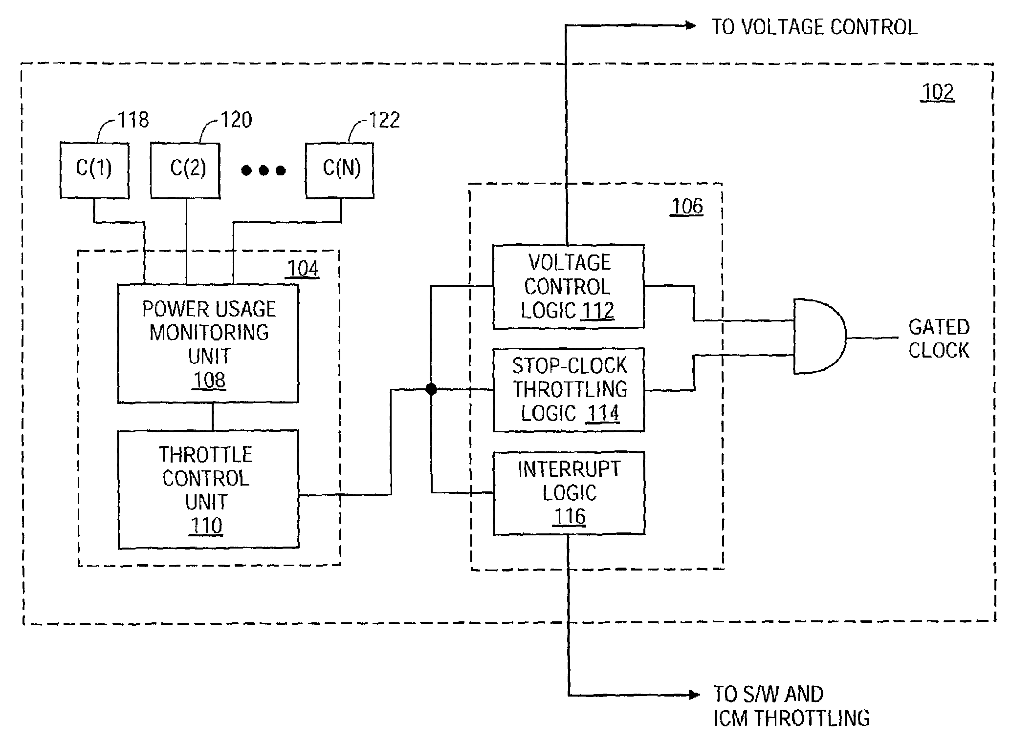
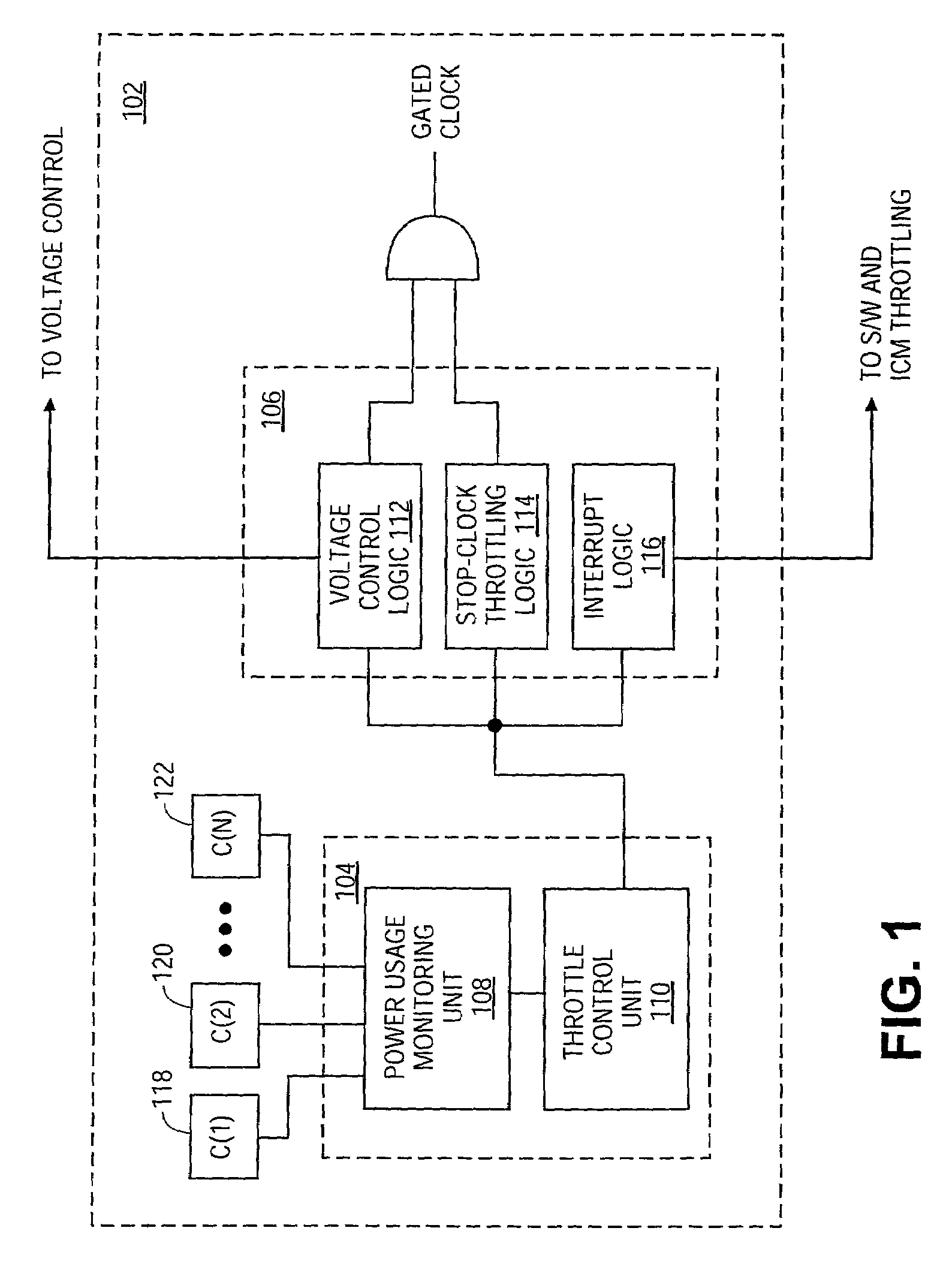
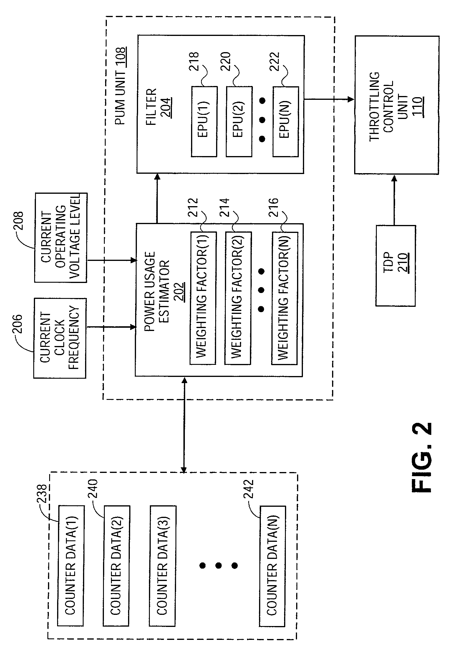
The present invention relates to thermal control for microprocessors. The invention uses a digital power monitoring system to estimate the amount of power consumed by a microprocessor during a given time interval. This estimation is based on the frequency of various activities occurring within the microprocessor. The invention dynamically activates throttling mechanisms to prevent the microprocessor from operating at high temperatures that may cause system degradation or exceed the system specification. The invention provides a deterministic behavior, resulting in a deterministic system behavior, unlike current thermal diodes that provide non-deterministic behavior. The technical effect of the invention is to improve the thermal control for microprocessors and prevent overheating while running typical applications.

Problems solved by technology

With the increasing complexity of new microprocessors, thermal control becomes more challenging.
A drawback to providing a microprocessor with extensive execution resources is that significant amounts of power are required to run the microprocessors.
Different execution units may consume more or less power, depending on their size and the functions they implement, but the net effect of packing so much logic onto a relatively small process chip is to create the potential for significant power dissipation problems.
When the junction temperature approaches the allowed maximum value, throttling may be activated to cool the microprocessor, resulting in a significant performance loss.
Currently used thermal diodes protect microprocessors from overheating situations, but may not be useful in mobile systems.
In general, original equipment manufacturers (OEMs) of mobile systems prefer not to support thermal diode based throttling in normal operating conditions while running typical applications.

Method used


Image

  • Deterministic power-estimation for thermal control
  • Deterministic power-estimation for thermal control
  • Deterministic power-estimation for thermal control

Examples


Embodiment Construction

[0012]In the following description, specific details are set forth in order to provide a thorough understanding of the present invention. However, it will be apparent to one skilled in the art that the present invention may be practiced without these specific details. In other instances, well-known circuits, structures and techniques have not been shown in detail in order to avoid obscuring the present invention.

[0013]A thermal control system is described. In one embodiment, a thermal control system is provided that uses a digital power monitoring for thermal control in computer systems. The digital monitoring of power is configured to estimate an amount of power used by a microprocessor. Based on the estimated power usage, the thermal control system controls the activation and deactivation of throttling mechanism to avoid unsafe junction temperature that may cause system degradation or that exceeds system specification.

[0014]It has been found than the amount of power consumed by a ...


PUM


Abstract

A system is described that includes a microprocessor and a thermal control subsystem. The microprocessor includes execution resources to support processing of instructions and consumes power. The microprocessor also includes at least one throttling mechanism to reduce the amount of heat generated by the microprocessor. The thermal control subsystem is configured to estimate an amount of power used by the microprocessor and to control the throttling mechanism based on the estimated amount of current power usage to ensure that junction temperature will not exceed the maximum allowed temperature.

Description

BACKGROUND[0001]1. Field of the Invention[0002]This invention relates to thermal control for microprocessors.[0003]2. Description of the Related Art[0004]With the increasing complexity of new microprocessors, thermal control becomes more challenging. Current microprocessors include extensive execution resources to support concurrent processing of multiple instructions. A drawback to providing a microprocessor with extensive execution resources is that significant amounts of power are required to run the microprocessors. Different execution units may consume more or less power, depending on their size and the functions they implement, but the net effect of packing so much logic onto a relatively small process chip is to create the potential for significant power dissipation problems.[0005]In conventional thermal control systems, junction temperature (Tj) on a die is observed to ensure that it does not exceed an allowed maximum value to avoid reliability issues. When the junction temp...

Claims


Application Information

Patent Timeline
Patent Type & Authority Patents(United States)
IPC IPC(8): G06F15/00G06F1/32
CPCG06F1/3203G06F1/324G06F1/3296G06F11/3062G06F11/3096G06F11/3024Y02B60/1285Y02B60/1217Y02D10/00
Inventor ORENSTIEN, DORONRONEN, RONNY
Owner RAKUTEN GRP INC
Learn More