Methods and apparatus for facilitating network splicing

a network splicing and network technology, applied in the field of systems and methods for transmitting compressed digital video data, can solve the problems of reducing the output video quality, reducing the bandwidth efficiency of bandwidth, and reducing the cost of bandwidth efficiency, so as to improve bandwidth efficiency, improve bandwidth efficiency, and simplify packet level switching

Active Publication Date: 2006-08-22
CISCO TECH INC
View PDF8 Cites 70 Cited by
  • Summary
  • Abstract
  • Description
  • Claims
  • Application Information

AI Technical Summary

Benefits of technology

[0014]In one embodiment, bitstream conditioning is accomplished in two stages involving three reference points. The first reference point is the original program encoder. This encoder will not create any splice points, its job is to encode video data at its best possible quality, adopting whatever I/P/B frame structure it deems necessary to accomplish this goal. The second reference point is the conditioning device, multiple of which typically are located away from the encoder but are sharing the same content. Each such device may have its own independent local content insertion schedule. Each of the conditioning network device feeds the third reference points—the splicers. Typically multiple splicers share the same network conditioners. The splicer may implement a simple packet level switch.
[0015]In another embodiment, there are two main ideas behind this invention. This first one is that by properly conditioning the broadcast bitstream downstream from the original encoding, it is possible to avoid having an original encoder unnecessarily produce to

Problems solved by technology

However, compressed video programs transmitted in a broadcast typically do not always have anchor frames placed in splicing locations for digital ad segments.
These mechanisms may all diminish output video quality.
Making more frequent splicing points in the bitstream would make it more likely that the subsequent insertion can be done, but it comes at the cost of decreased bandwidth efficiency since I frames consumes considerably mo

Method used


Image

  • Methods and apparatus for facilitating network splicing
  • Methods and apparatus for facilitating network splicing
  • Methods and apparatus for facilitating network splicing

Examples


Embodiment Construction

[0033]The present invention will now be described in detail with reference to a few preferred embodiments thereof as illustrated in the accompanying drawings. In the following description, numerous specific details are set forth in order to provide a thorough understanding of the present invention. It will be apparent, however, to one skilled in the art, that the present invention may be practiced without some or all of these specific details. In some instances, well known process steps and / or structures have not been described in detail in order to not unnecessarily obscure the present invention.

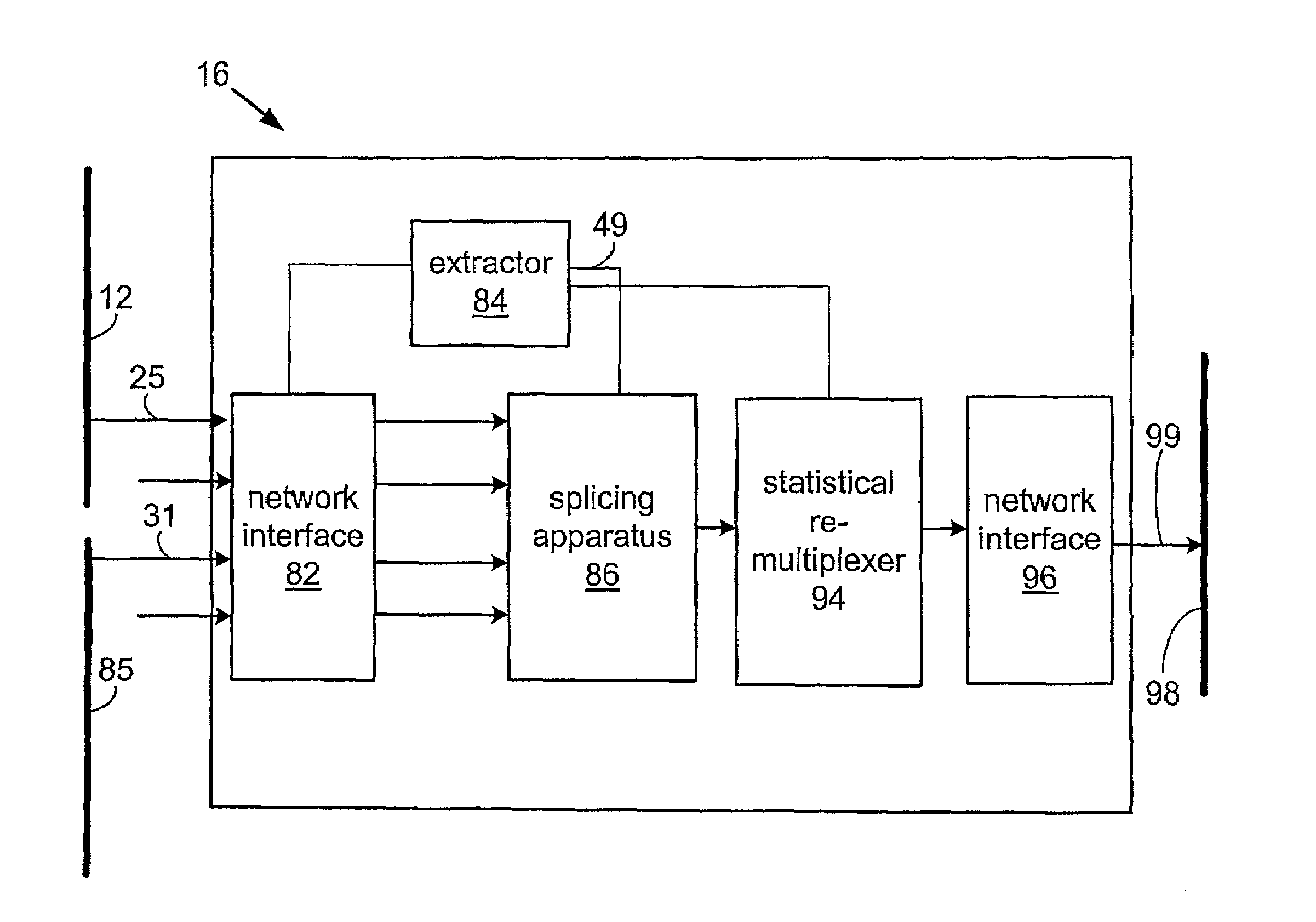
[0034]The present invention provides systems and methods for providing compressed video data from multiple bit streams. The systems and methods described herein apply a two-stage strategy. In the first stage, a conditioning step is performed on a bit stream comprising compressed video data which outputs a conditioned bit stream that is able to receive digital insertions without subsequent d...


PUM


Abstract

The invention provides systems and methods for providing compressed video data from multiple bit streams. The systems and methods apply a two-stage strategy. In the first stage, a conditioning step is performed on a bit stream comprising compressed video data which outputs a conditioned bit stream that is able to receive digital insertions without subsequent decompression of the compressed video data or removal from network packets. The conditioning includes recoding an incoming bit stream such that compressed video data in the bit stream immediately before and after a splice point does not have temporal reliance across the splice point. In the second stage, e.g., at a downstream network device, splicing of compressed video data from a second bit stream into the conditioned bit stream is performed. The splicing takes advantage of the changes made to the conditioned bit stream and may occur at the network packet level.

Description

CROSS-REFERENCE TO RELATED APPLICATION[0001]This application claims priority under 35 U.S.C. § 119(e) from co-pending U.S. Provisional Patent Application Ser. No. 60 / 346,234 entitled “Methods and Apparatus for Facilitating Network Splicing” filed on Oct. 19, 2001 and naming Ji Zhang et al. as inventors, which is incorporated by reference herein for all purposes.BACKGROUND OF THE INVENTION[0002]The present invention relates generally to systems and methods for transmitting data. More specifically, the present invention relates to systems and methods for transmitting compressed digital video data in a manner that allows downstream network devices to splice multiple compressed video bit streams using network packet level manipulation.[0003]There are presently a variety of different communication channels for transmitting or transporting video data. For example, communication channels such as coaxial cable distribution networks, digital subscriber loop (DSL) access networks, ATM network...

Claims


Application Information

Patent Timeline
IPC IPC(8): H04N7/173
CPCH04N21/2343H04N21/23424
Inventor ZHANG, JIDAVIS, JOSEPH
Owner CISCO TECH INC
Why Eureka
Try Eureka