Static mixer and process for mixing at least two fluids

a technology of mixer and fluid, applied in the direction of filtration separation, separation process, instruments, etc., can solve the problems of large structure, large narrow channel, and promote relatively high pressure loss, and achieve the effect of minimal pressure loss and efficient mixing

Inactive Publication Date: 2006-08-29
UOP LLC
View PDF25 Cites 19 Cited by
  • Summary
  • Abstract
  • Description
  • Claims
  • Application Information

AI Technical Summary

Benefits of technology

[0009]In a first embodiment, the present invention is an apparatus for mixing at least two fluid streams, a first fluid stream and a second fluid stream, efficiently and with minimal pressure loss. The apparatus comprises a first supply conduit having a first supply conduit receiving end for receiving the first fluid. The apparatus further comprises a second supply conduit having a second supply conduit receiving end for receiving the second fluid. The apparatus further comprises a mixing chamber in fluid communication with the first and second supply conduits at first and second supply conduit discharge ends opposite the first and second supply conduit receiving ends. One of the first or second supply conduit discharge ends leads substantially tangentially into the mixing chamber and the other of the first or second supply conduit discharge ends leads substantially radially into the mixing chamber. The discharge ends lie substantially within an inlet plane and are distributed about the circumference of the mixing chamber. The apparatus further comprises a mixing chamber outlet for discharging a mixed stream of the first and second fluids from the mixing chamber, the mixing chamber outlet in fluid communication with the central region of the mixing chamber. The mixing chamber outlet lies in an outlet plane that is substantially perpendicular to the inlet plane.

Problems solved by technology

A drawback with this configuration is that the narrow channel must be sufficiently long to achieve full, intimate mixing.
This requires a large structure and promotes relatively high pressure loss.

Method used


Image

  • Static mixer and process for mixing at least two fluids
  • Static mixer and process for mixing at least two fluids
  • Static mixer and process for mixing at least two fluids

Examples


examples 1 – 5

EXAMPLES 1–5

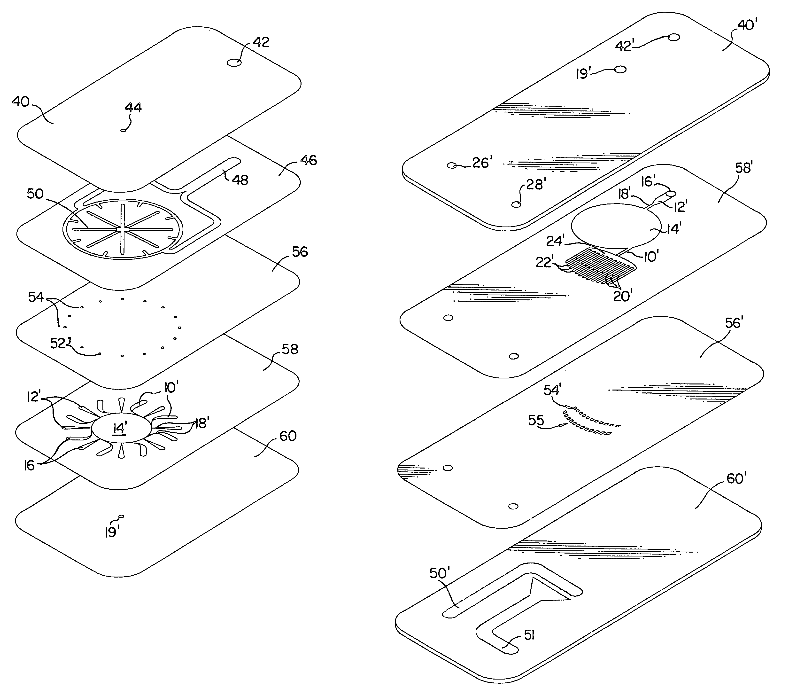
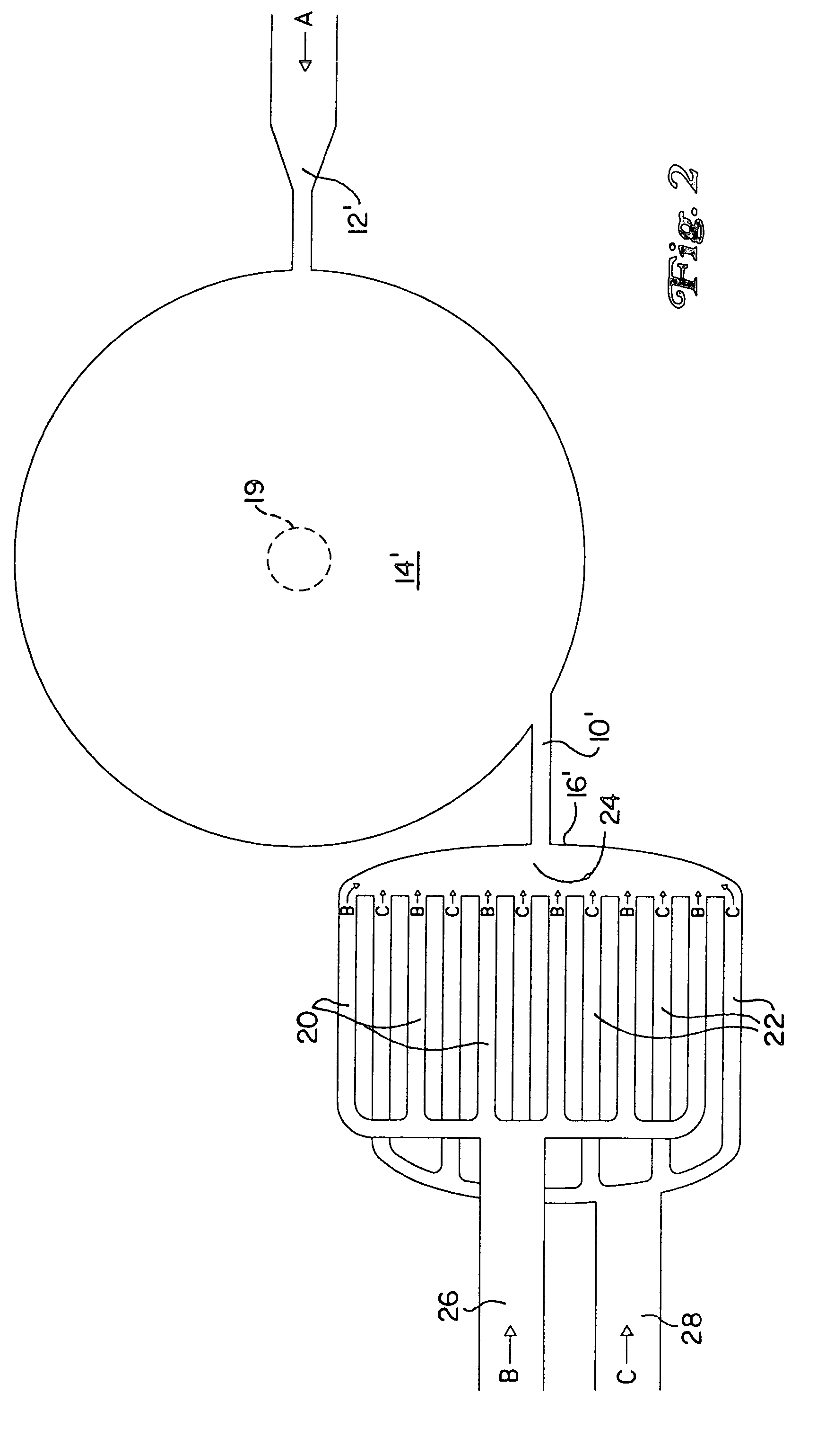
[0069]A static mixer comprising an arrangement of stacked plates and using the principle of cyclone mixing as described previously was constructed of glass to observe cyclone formation under various conditions. Water and air were injected into the mixing chamber in tangential and radial directions, respectively, with respect thereto. A high speed camera with digital image processing was used to observe whether a helical flow of the flowing liquid was established. This was readily determined from observing the path of gas bubbles within the water stream . The results of these experiments are summarized in Table 1.

[0070]

TABLE 1Kinetic EnergyCycloneWater FlowAir FlowRatioFormationExample #(ml / hr)(ml / hr)water / air(Y / N)11007,8000.04N260012,0000.66Y390012,0001.49Y46003,6007.41Y59003,60016.7Y

[0071]From these results, the desired spiral flow formation was obtained with a kinetic energy ratio of liquid / gas of 0.66 and higher. The lower bound of the kinetic energy ratio of the tang...


PUM


Abstract

A novel mixing apparatus and process for mixing at least two fluids are disclosed. Excellent mixing and superior pressure drop characteristics are achieved in a device comprising at least two supply channels to feed a mixing chamber and create a vortex. The alignment of the supply channels is such that fluids are introduced into the chamber at both tangential and radial directions. In the case of gas / liquid mixing, particularly advantageous is the injection of the liquid stream tangentially and the gas stream radially. When two liquid streams are mixed, it is desirable to distribute them into fine, interdigitated channels prior to introduction into a supply channel and finally into the chamber. The mixed stream is generally withdrawn from the center of the swirling vortex and in a direction perpendicular to the plane of the vortex.

Description

CROSS-REFERENCE TO RELATED APPLICATION[0001]This application is a continuation-in-part of U.S. application Ser. No. 09 / 850,470; filed May 7, 2001 now U.S. Pat. No. 6,655,829, and is incorporated by reference in its entirety.FIELD OF THE INVENTION[0002]The present invention relates to a novel mixer and process for mixing at least two fluids. The mixer comprises a mixing chamber, at least two conduits to supply fluids in both tangential and radial directions into the chamber, and a mixing chamber outlet to discharge a stream of mixed fluids.BACKGROUND OF THE INVENTION[0003]When mixing at least two fluids, the objective is to achieve a uniform distribution as rapidly as possible. It is advantageous to use the static mixers described by W. Ehrfeld, V. Hessel, H. Löwe in Microreactors, New Technology for Modern Chemistry, Wiley-VCH 2000, p. 41–85. Known static mixers achieve mixing times for liquids between several milliseconds and 1 second by generating alternate adjacent fluid layers o...

Claims


Application Information

Patent Timeline
Patent Type & Authority Patents(United States)
IPC IPC(8): B01F5/04B01F13/00B81B1/00B01F5/00B01F5/06B01J19/00B01J19/24
CPCB01F5/04B01F5/0604B01F5/064B01F13/0064B01F13/0066B01F13/0094B01J19/0093B01J19/249B01J2219/2493B01F2005/002B01J2219/00835B01J2219/247B01J2219/2474B01J2219/2488B01F2005/0014B01F2025/9122B01F2025/914B01F25/30B01F25/422B01F25/432B01F33/3017B01F33/3012B01F33/304
Inventor VANDEN BUSSCHE, KURT M.ABDO, SUHEIL F.HESSEL, VOLKERLOWE, HOLGERHARDT, STEFFEN
Owner UOP LLC
Why Eureka
Try Eureka