Integral cover bucket design

a technology of integral covers and steam turbines, applied in the design field of steam turbine buckets with integral covers, can solve the problems of stress corrosion cracking, corrosion damage of metal surfaces in the tip area, erosion and other problems, to achieve the effect of reducing aerodynamic losses, avoiding erosion and corrosion of steam turbine buckets, and improving reliability and efficiency

Inactive Publication Date: 2006-08-29
GENERAL ELECTRIC CO
View PDF3 Cites 31 Cited by
  • Summary
  • Abstract
  • Description
  • Claims
  • Application Information

AI Technical Summary

Benefits of technology

[0004]The present invention identifies an improved bucket tip and cover shape that avoids erosion and corrosion of the steam turbine bucket and reduce aerodynamic losses, thus improving the reliability and efficiency of the steam turbine. This design change is achieved without impacting other features that are critical to the performance of the turbine and reliability of the bucket.
[0005]In an exemplary embodiment, the last stage turbine buckets have integral covers disposed at the tip of the buckets that are generally similar to the known covers, but with a subtle yet significant shape change as further described below. To solve the problems experienced with the existing cover design, the cover has been modified to the extent that a radial step is formed between the airfoil leading edge tip and the cover top surface that eliminates the above-described pocket area, thus reducing moisture entrapment potential and also reducing aerodynamic drag force or aerodynamic losses. In one variant, the radial surface portion of the step is curved toward the adjacent bucket cover surface. In a second variant, the radial surface portion of the step is curved more severely to substantially smoothly merge with the adjacent bucket cover surface. The precise shape of the step may be optimized to balance the stress level, addition of mass and the impact on the aerodynamic design.
[0008]In still another aspect, the invention provides a method of eliminating a moisture-trapping pocket between adjacent top covers at radially outer ends of respective airfoil portions of turbine buckets comprising: a) radially shortening leading edges of the turbine buckets to create radial steps between the leading edges and top surfaces of the tip covers; and b) cutting radial surface portions of the radial steps such that the radial surface portions more smoothly merge with adjacent radial surfaces at trailing edges of adjacent buckets.

Problems solved by technology

The action of high speed, wet steam flow on the buckets can produce erosion, and can contribute to corrosion damage of the metal surfaces in the tip areas.
The presence of moisture on these contact areas can contribute to stress corrosion cracking.
The trapped moisture in the pocket area can cause damage to the buckets themselves as well as the damping contact surfaces of the covers.

Method used


Image

  • Integral cover bucket design
  • Integral cover bucket design
  • Integral cover bucket design

Examples


Embodiment Construction

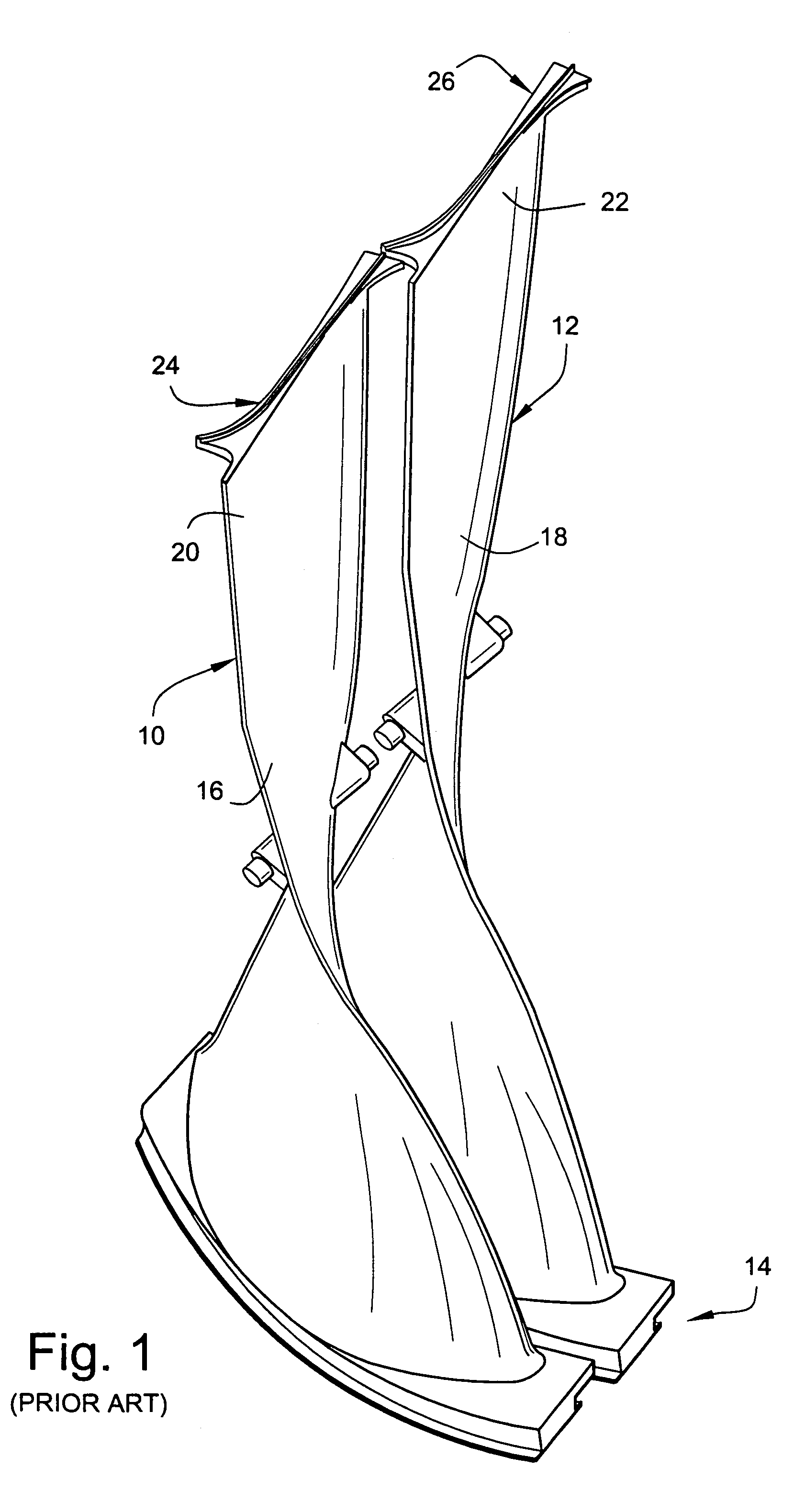
[0014]With reference to FIG. 1, a plurality (two shown) of like turbine blades or buckets 10, 12 are secured to a turbine rotor wheel (not shown) by means of a dovetail or other suitable joint generally indicated at 14. The buckets 10, 12 extend a full 360° about the turbine wheel, thereby forming a “row” of buckets. Each bucket in the row is generally identical, though occasionally the last bucket (or “notch blade”) and two buckets adjacent to the notch blade can have some geometrical differences to facilitate assembly. As is well understood, the dovetail or other joints 14 are designed for mating and sliding engagement with a complementary dovetail or other shape formed on the rim of the rotor wheel. The type of bucket dovetail and the manner of loading the buckets onto the wheel may vary and, in any event, is not significant to this invention.

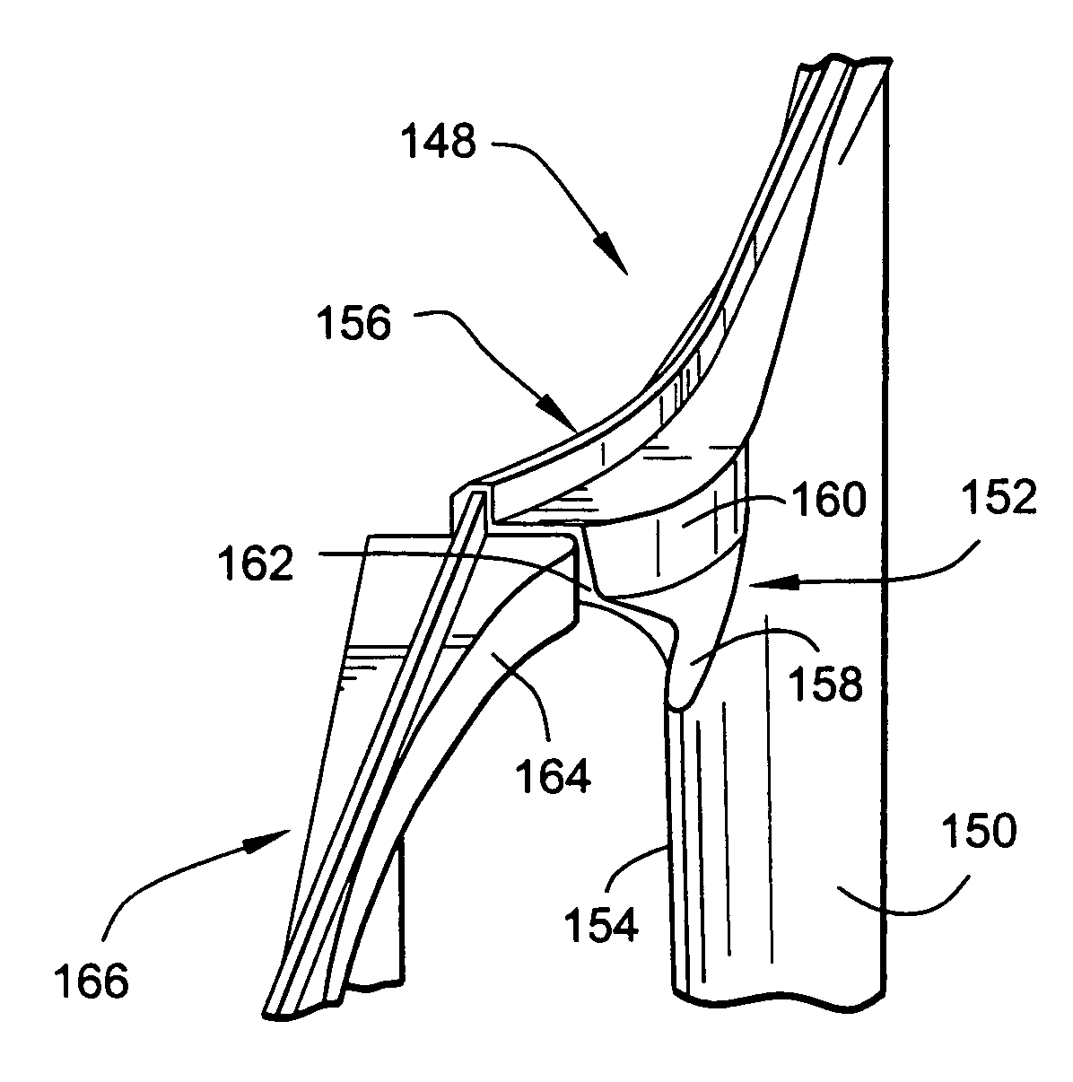
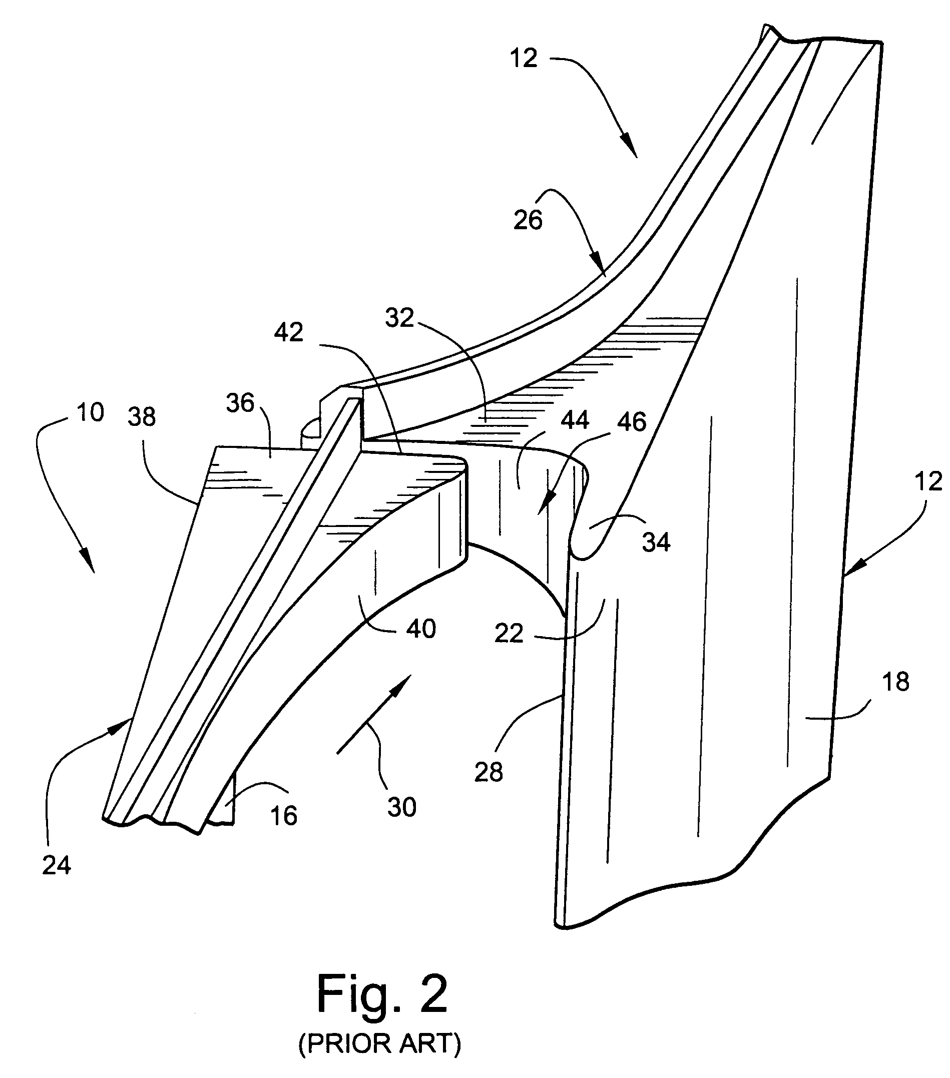
[0015]Blade portions 16, 18 of the buckets 10, 12, respectively, extend upwardly from the dovetail or shank portions 19, 21 to respective t...


PUM


Abstract

A bucket for use on a steam turbine rotor wheel, the bucket comprising a shank portion and an airfoil portion, the airfoil portion having a radially outer tip with a tip cover adapted to be engaged, in use, by a similar tip cover on an adjacent bucket, wherein a radial step is formed in the tip cover and the airfoil portion along a leading edge of the airfoil portion.

Description

BACKGROUND OF THE INVENTION[0001]This invention relates to steam turbines and more specifically, to the design of last-stage steam turbine buckets with integral covers.[0002]The tip areas of last-stage steam turbine buckets or blades with integral covers operate in a wet steam condition, typically with supersonic relative velocity between the steam flow and the buckets. The action of high speed, wet steam flow on the buckets can produce erosion, and can contribute to corrosion damage of the metal surfaces in the tip areas. The covers between adjacent buckets contact each other during operation by virtue of the bucket's rotation caused by the untwisting effect of the applied centrifugal forces. Connection or contact of the integrally covered buckets during operating conditions enhances the rigidity of the bucket structure and improves vibration damping. The presence of moisture on these contact areas can contribute to stress corrosion cracking. The design of the last stage bucket, th...

Claims


Application Information

Patent Timeline
Patent Type & Authority Patents(United States)
IPC IPC(8): F03B3/12F01D5/14F01D5/20F01D5/22
CPCF01D5/141F01D5/225F05D2260/96F01D1/00F01D5/02F01D5/06F01K21/00
Inventor BARB, KEVIN JOSEPHHOFER, DOUGLAS CARLMUJEZINOVIC, AMIRGINESSIN, LEONID YULYEVICH
Owner GENERAL ELECTRIC CO
Why Eureka
Try Eureka