High density connector with enhanced structure

Inactive Publication Date: 2006-08-29
HON HAI PRECISION IND CO LTD
View PDF42 Cites 62 Cited by
  • Summary
  • Abstract
  • Description
  • Claims
  • Application Information

AI Technical Summary

Benefits of technology

[0008]Accordingly, it is an object of the present invention to provide a high density connector with posi

Problems solved by technology

Specifically, electrical connectors having higher densities and pin counts require careful consideration of the problems which result from decreasing the distance between contacts.
Understandably, greater density cannot sacrifice electrical or mechanical performance of a connector.
A difficulty in designing high density connectors having a low-mated height is in maintaining proper alignment of the contact elements of engaged connectors so as to insure reliable electrical connections therebetween.
However, the problem to maintain proper alignment of contacts during mating procedure is not solved and no particular enhanced structure is provided to insure a reliable electrical connection from the fi

Method used


Image

  • High density connector with enhanced structure
  • High density connector with enhanced structure
  • High density connector with enhanced structure

Examples


Embodiment Construction

[0021]Reference will now be made to the drawing figures to describe the present invention in detail.

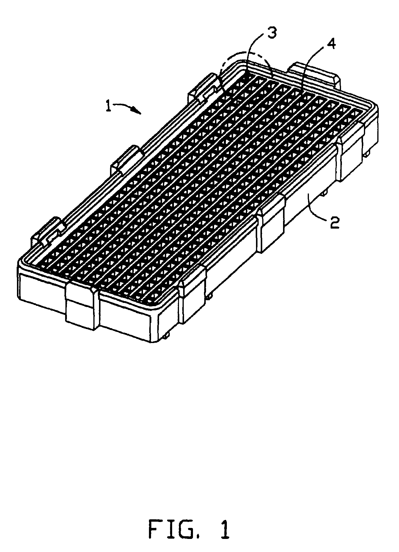
[0022]With reference to FIG. 1, an electrical connector assembly 100 in accordance with the present invention, which is adapted for interconnecting two circuit boards (not shown), comprises a receptacle 1 mounting on a first circuit board and a plug 9 mounting on a second board and mating with the receptacle 1.

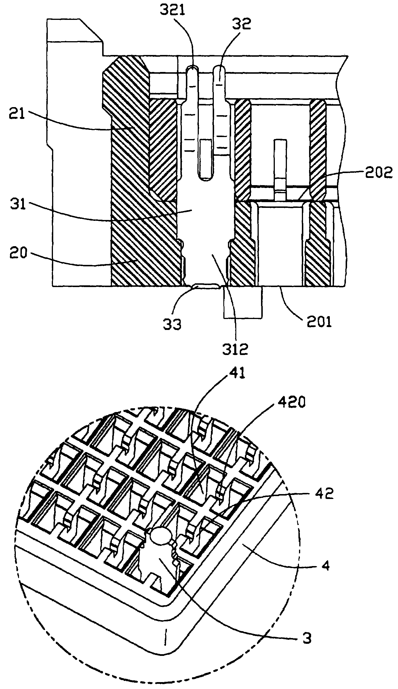
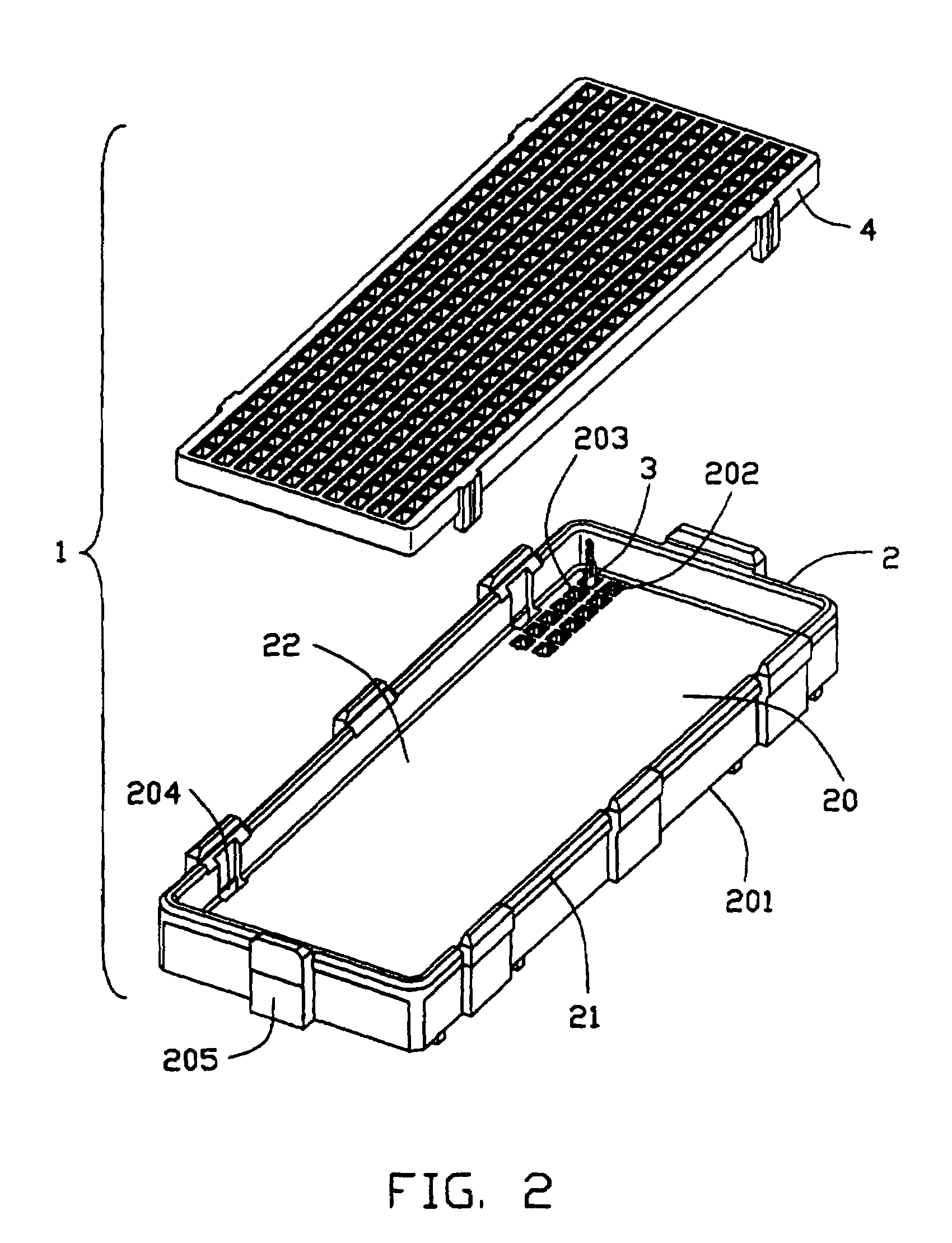
[0023]As seen in FIGS. 2–3, the receptacle 1 is provided with a dielectric housing 2, a plurality of conductive contacts 3 received in the housing 2, and a stabilizer 4 detachably assembled onto the housing 2. The dielectric housing 2 has a base 20, described throughout as a plate, side walls 21 extending upwardly from periphery edges of the base plate 20, and a receiving cavity 22 defined therebetween which provides space for receiving the stablizer 4.

[0024]The base plate 20 has a lower mounting face 201 confronting to the printed circuit board, a parallel, upper receiving face...


PUM


Abstract

An electrical connector (1) includes a housing (2) and conductive contacts (3) partially positioned in the housing. The housing has a base wall (20) and side wall (21). The top edge of the side wall has a thickness larger than other portion of the side wall. Each contact has a body portion (31) and a pair of cantilevered beams (32) extending from the body portion. A stabilizer (4) is assembled in the housing. The stabilizer provides a general flat planar surface (40) on a top and defines a number of cavities (41) exposed to the surface. The cantilevered beams extend through the cavities of the stabilizer and exposed partially outside the surface thereof.

Description

BACKGROUND OF THE INVENTION[0001]1. Field of the Invention[0002]The present invention generally relates to a low profile electrical connector for interconnecting two printed circuit boards, and particularly to a high speed, high density connector having enhanced structure for insuring a reliable signal transmission.[0003]2. Description of Related Art[0004]Continued advances in the design of electronic devices for data processing and communications systems have placed rigorous demands on the design of electrical connectors. Specifically, electrical connectors having higher densities and pin counts require careful consideration of the problems which result from decreasing the distance between contacts. Understandably, greater density cannot sacrifice electrical or mechanical performance of a connector.[0005]A difficulty in designing high density connectors having a low-mated height is in maintaining proper alignment of the contact elements of engaged connectors so as to insure reliabl...

Claims


Application Information

Patent Timeline
IPC IPC(8): H01R12/00H01R12/55
CPCH01R13/40H01R12/716H05K7/1069
Inventor KORSUNSKY, IOSIF R.GILLESPIE, BRIAN J.
Owner HON HAI PRECISION IND CO LTD
Why Eureka
Try Eureka