Electrical block positioning devices and methods of use therefor

a positioning device and electric block technology, applied in the field of electric block positioning devices and, can solve the problems of affecting the normal heart rhythm, the clotting of blood inside the atrium, and the clotting of blood vessels can be very serious, and achieve the effect of better conformity

a positioning device and electric block technology, applied in the field of electric block positioning devices and, can solve the problems of affecting the normal heart rhythm, the clotting of blood inside the atrium, and the clotting of blood vessels can be very serious, and achieve the effect of better conformity

US7097643B2Inactive Publication Date: 2006-08-29SYNTACH AG

Image

  • Electrical block positioning devices and methods of use therefor
  • Electrical block positioning devices and methods of use therefor
  • Electrical block positioning devices and methods of use therefor

Examples


Embodiment Construction

Guiding Catheter

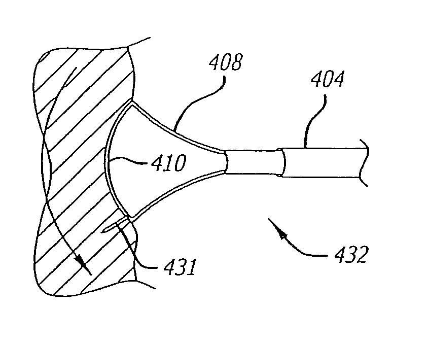
[0058]The ostium of the pulmonary veins has a highly variable geometry from one patient to another and this presents difficulty in reliably treating atrial arrhythmias using previous ablation methods. To address this problem, guiding or anchoring devices are used to position and secure such ablation devices used to create electrical block.

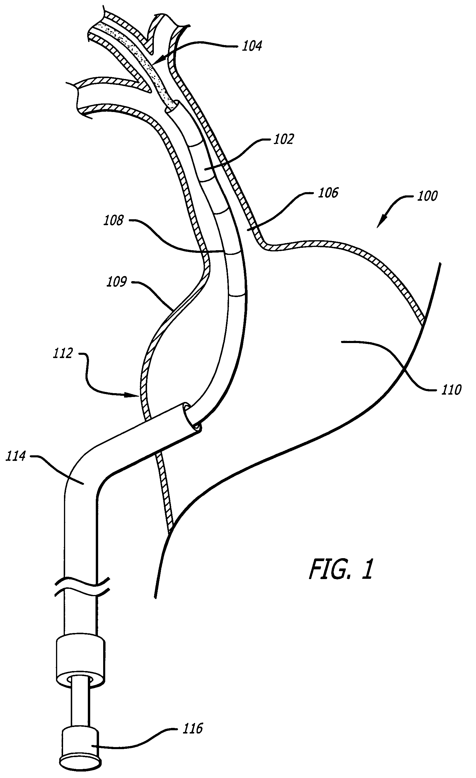
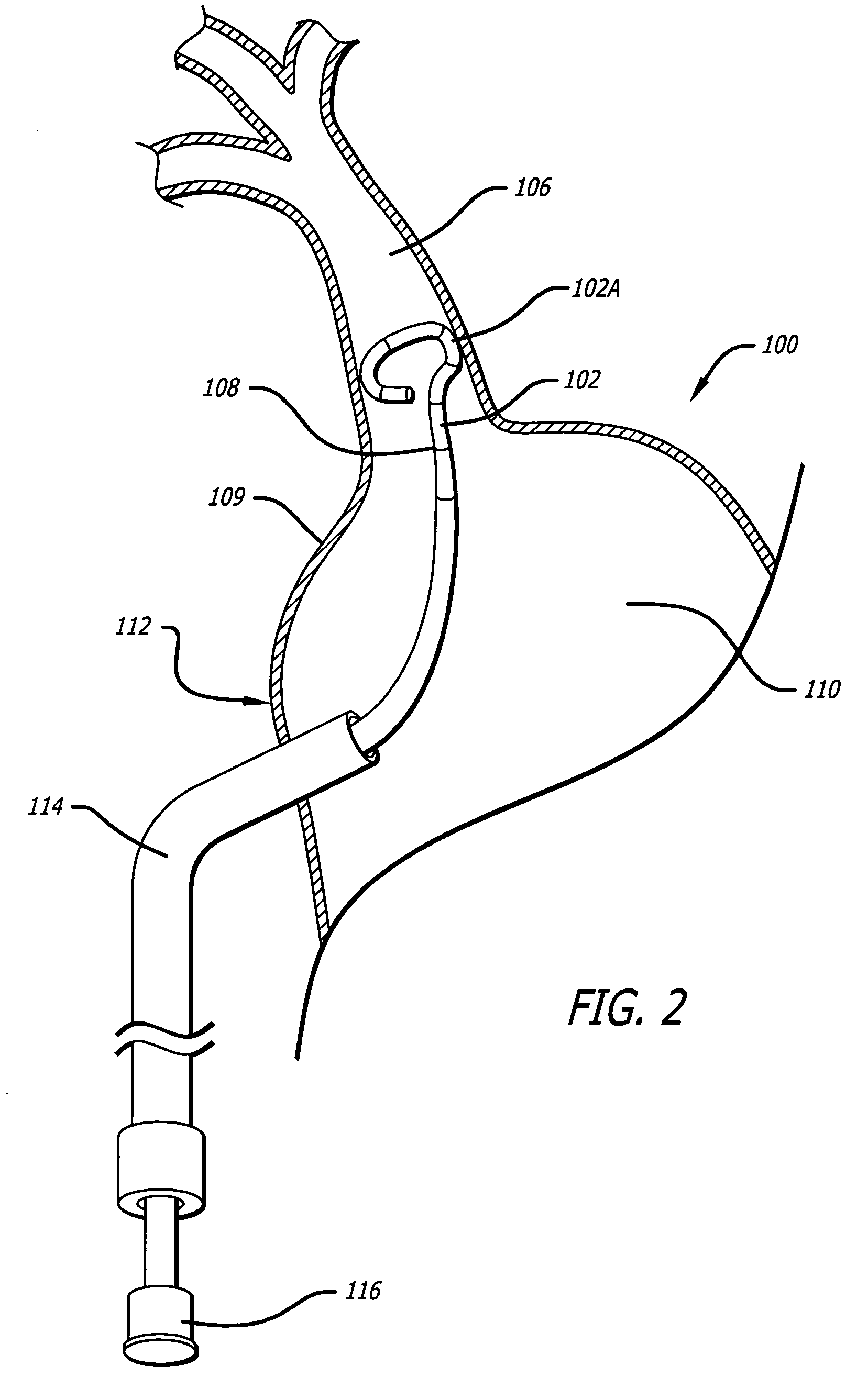
[0059]One guiding device according to the present invention is a guiding catheter 102, seen in FIGS. 1–3, which may be positioned within the pulmonary veins 106. The guiding catheter 102 has a heat-set distal tip which causes it to self curl into a loop shape 102a, best seen in FIG. 2. Marker rings 108 are spaced along the distal end of the guiding catheter 102 and are typically composed of a radiopaque material that allows visibility during a radio imaging procedure.

[0060]As with some percutaneous transeptal procedures, the guiding catheter 102 is deployed through the heart septum 112 and into the left atrium 110 by way of transept...


PUM


Abstract

The present invention provides positioning mechanisms for devices that cause conduction blocks or ablation in desired areas of tissue. The positioning mechanisms allow for variable geometry of the target sites and enable more accurate therapy at the tissue site.

Description

CROSS REFERENCE TO RELATED APPLICATIONS[0001]This application claims the benefit of U.S. Provisional Application No. 60 / 451,821, entitled Positioning Device For Guiding Device Delivery Or Interventions In Pulmonary Veins Or Other Large Body Vessels, filed Mar. 3, 2003; and U.S. Provisional Application No. 60 / 467,298, entitled Improved Methods And Devices For Creating Electrical Block At Specific Targeted Sites In Cardiac Tissue, filed May 1, 2003, the entire contents of each being hereby incorporated by reference.BACKGROUND OF THE INVENTION[0002]Pumping of the human heart is caused by precisely timed cycles of compartmental contractions of the heart muscle which lead to an efficient movement of blood into the heart and out to the various bodily organs and back again to the heart. These precisely timed cycles are controlled and directed by electrical signals that are conducted through the cardiac tissue and can be referred to as pacing signals.[0003]The sinoatrial node (SA node) is t...

Claims


Application Information

Patent Timeline
29 Aug 2006
Publication
US7097643B2
IPC
A61B18/18; A61B17/00; A61B17/34; A61B18/14; A61B19/00; A61F; A61F6/00
CPC
A61B18/1492; A61M25/0068; A61M25/0082; A61B18/02; C08L2201/12; A61B18/18; A61B19/201; A61B19/54
Inventors
CORNELIUS, RICHARD; SWANSON, WILLIAM