High performance support-separator for communications cables

a technology of support and separation, which is applied in the direction of insulated conductors, cables, instruments, etc., can solve the problems of increased cross-talk, unsatisfactory energy transfer between conductor pairs, and shielded cables, so as to improve the next control, and reduce the need for complex effects

Inactive Publication Date: 2006-08-29
CABLE COMPONENTS GROUP
View PDF11 Cites 270 Cited by
  • Summary
  • Abstract
  • Description
  • Claims
  • Application Information

AI Technical Summary

Benefits of technology

[0038]Yet another embodiment of the invention allows for interior corrugated clearance channels provided by the anvil-shaped sections of the core support-separator. This corrugated internal section has internal axial grooves that allow for separation of conductor pairs from each other or even separation of single conductors from each other as well as separation of optical conductors from conventional metal conductors. Alternatively, the edges of said grooves may allow for separation thus providing a method for uniformly locating or spacing the conductor pairs with respect to the channel walls instead of allowing for random floating of the conductor pairs.
[0039]Each groove can accommodate at least one twisted pair. In some instances, it may be beneficial to keep the two conductors in intimate contact with each other by providing grooves that ensure that the pairs are forced to contact a portion of the wall of the clearance channels. The interior support provides needed structural stability during manufacture and use. The grooves also improve NEXT control by allowing for the easy spacing of the twisted pairs. The easy spacing lessens the need for complex and hard to control lay procedures and individual shielding. Other significant advantageous results such as: improved impedance determination because of the ability to precisely place twisted pairs: the ability to meet a positive ACR value from twisted pair to twisted pair with

Problems solved by technology

Energy transferred between conductor pairs is undesirable and referred to as crosstalk.
Such close spacing increases the amount of undesirable cross-talk that occurs.
Shielded cable, although exhibiting better cross-talk isolation, is more difficult, time consuming and costly to manufacture, install, and terminate.
Individually shielded pairs must generally be terminated using special tools, devices and techniques adapted for the job, also increasing cost and difficulty.
However, UTP fails to achieve superior cross-talk isolation such as required by the evolving higher frequency standards for data and other state of the art transmission cable systems, even when varying pair lays are used.
The various pairs of the cable are therefore separated from each other, but each is only partially shielded, which is not so effective as shielding around each pair and is not always satisfactory.
However, these core types can add substantial cost to the cable, as well as excess material mass which forms a potential fire hazard, as explained below, while achieving a crosstalk reduction of typically 3 dB or more.
This undesirable separation contributes to increased structural return loss (SRL) and more variation in impedance.
This method has been proven impractical because such tight lays are expensive and greatly limits the cable manufacturer's throughput and overall production yield.
While the above described conventional cable, including the Belden 1711A cable design, due in part to their use of fluorinated polymers, meets all of the above design criteria, the use of fluorinated polymers is extremely expensive and may account for up to 60% of the cost of a cable designed for plenum usage.
A solid core of these communications cables contributes a large volume of fuel to a potential c

Method used


Image

  • High performance support-separator for communications cables
  • High performance support-separator for communications cables
  • High performance support-separator for communications cables

Examples


Embodiment Construction

[0089]The following description will further help to explain the inventive features of the cable and the interior support portion of the cable.

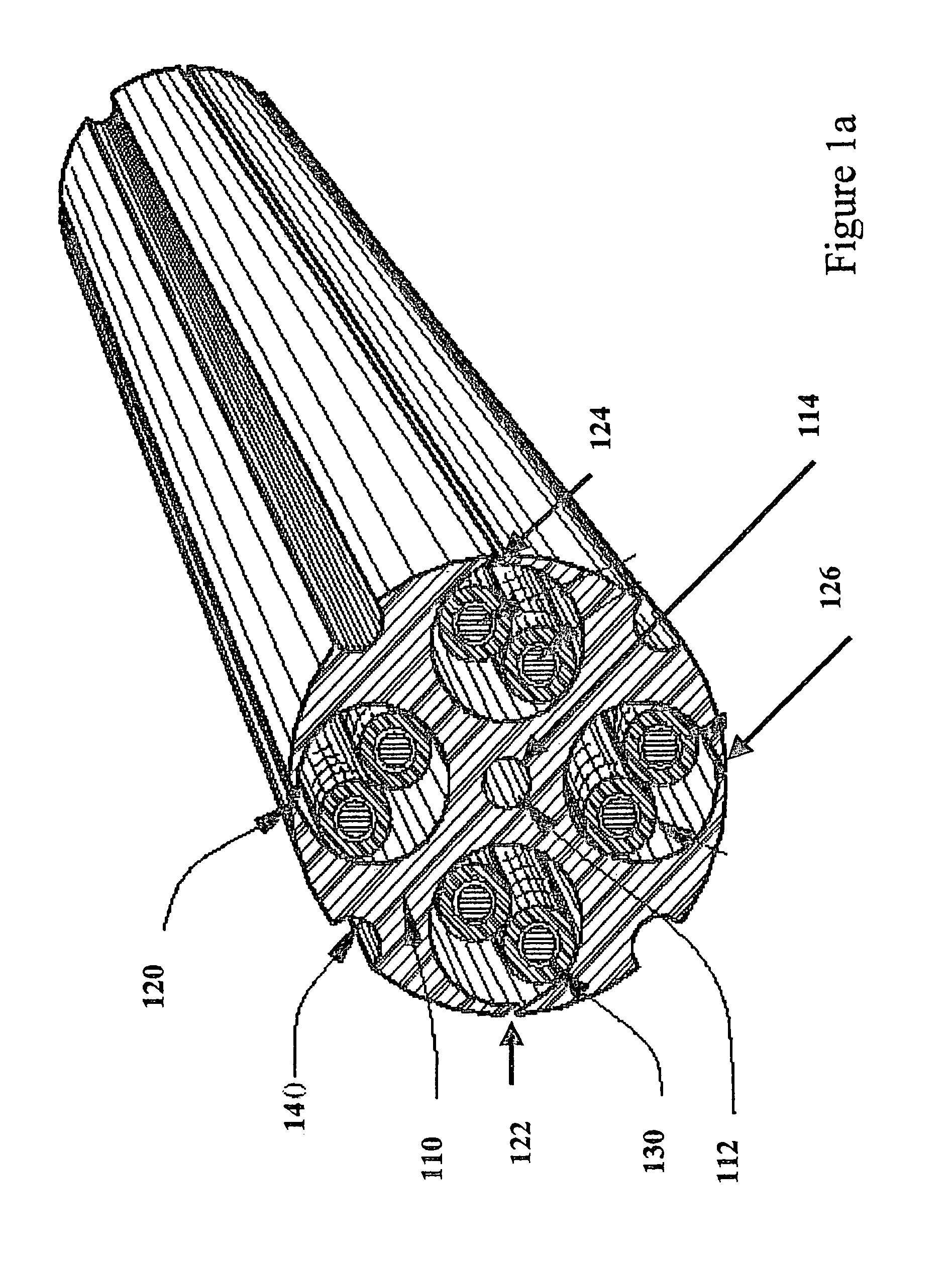
[0090]FIG. 1a is a top-right view of one embodiment of this invention. The shown embodiment has an interior support shown as an anvil-shaped separator (110). The interior support anvil-shaped separator, shown in more detail in FIGS. 3 and 4, runs along the longitudinal length on the cable. The interior support anvil-shaped separator, hereinafter, in the detailed description, referred to as the “anvil-shaped separator”, has a central region (112) extending along the longitudinal length of the cable. The center region includes a cavity that runs the length of the separator in which a strength member (114) may be inserted. Channels 120, 122, 124, and 126 extend along the length of the anvil-shaped separator and provide compartments for conductors (130).

[0091]A strength member may be added to the cable. The strength member (114) in the shown embo...


PUM


Abstract

The present invention includes a high performance communications cable for transmission media that includes core support-separators which define clearance channels to maintain spacing between transmission media or transmission media pairs. The core support-separator can be either interior to a cable jacket or be employed singularly without the benefit of a jacket and extends along the longitudinal length of the communications cable. The core support-separator has a central region that may include flap-tops along the radial edge that are available for partial or complete sealing of the clearance channels during manufacturing operations. The central region may also include a hollow center portion and include various geometric shapes to provide proper spacing between conductors. Each of the defined clearance channels allow for disposal therein of metal conductors and/or optical fibers.

Description

CLAIM TO PRIORITY[0001]This application is a continuation in part of and Applicants hereby claim priority under all rights to which they are entitled under 35 U.S.C. Section 120 based upon the U.S. application Ser. No. 09 / 939,375 now U.S. Pat. No. 6,639,152 filed on Aug. 25, 2001 and based on a 35 U.S.C. § 371 filing of PCT / USS02 / 13831 application filed on May 1, 2002 which designates the United States as the receiving office.FIELD OF INVENTION[0002]This invention relates to high performance multi-media communications cables utilizing paired or unpaired electrical conductors or optical fibers. More particularly, it relates to cables having a central core defining singular or plural individual pair channels. The communications cables have interior core support-separators that define a clearance through which conductors or optical fibers may be disposed.BACKGROUND OF THE INVENTION[0003]Many communication systems utilize high performance cables normally having four pairs or more that t...

Claims


Application Information

Patent Timeline
IPC IPC(8): H01B7/00H01B11/04
CPCG02B6/4435H01B11/06H01B11/04G02B6/4495G02B6/4431
Inventor GLEW, CHARLES A.
Owner CABLE COMPONENTS GROUP
Why Eureka
Try Eureka