Method and apparatus for scanning three-dimensional objects

a three-dimensional object and object technology, applied in the field of optical scanners, can solve the problems of difficult conformal mapping of two-dimensional color information onto the three-dimensional surface model, difficult to solve the problem of associating color information with three-dimensional objects, and complicated process of mapping 2-d color information to 3-d position information, etc., to achieve the effect of enhancing system accuracy and reducing system cos

Inactive Publication Date: 2006-08-29
WAVEWORX
View PDF13 Cites 86 Cited by
  • Summary
  • Abstract
  • Description
  • Claims
  • Application Information

AI Technical Summary

Benefits of technology

[0018]The present inventions provides a system and method for obtaining 3-D surface information that is linked to color information without the need to conformally map 2-D color data onto a 3-D surface. The accuracy of the system is enhanced by the use of color data ...

Problems solved by technology

The problem of associating color information with three dimensional (“3-D”) objects is not so easily solved.
The mapping of the 2-D color information to the 3-D position information is a complicated process which is prone to significant error.
The problem of conformally mapping the two-dimensional color information onto the three dimensional surface model is difficult and it is common for mismatching of color information with the three dimensional points to occur.
The photograph cannot simply be projected onto the bust to transfe...

Method used


Image

  • Method and apparatus for scanning three-dimensional objects
  • Method and apparatus for scanning three-dimensional objects
  • Method and apparatus for scanning three-dimensional objects

Examples


Embodiment Construction

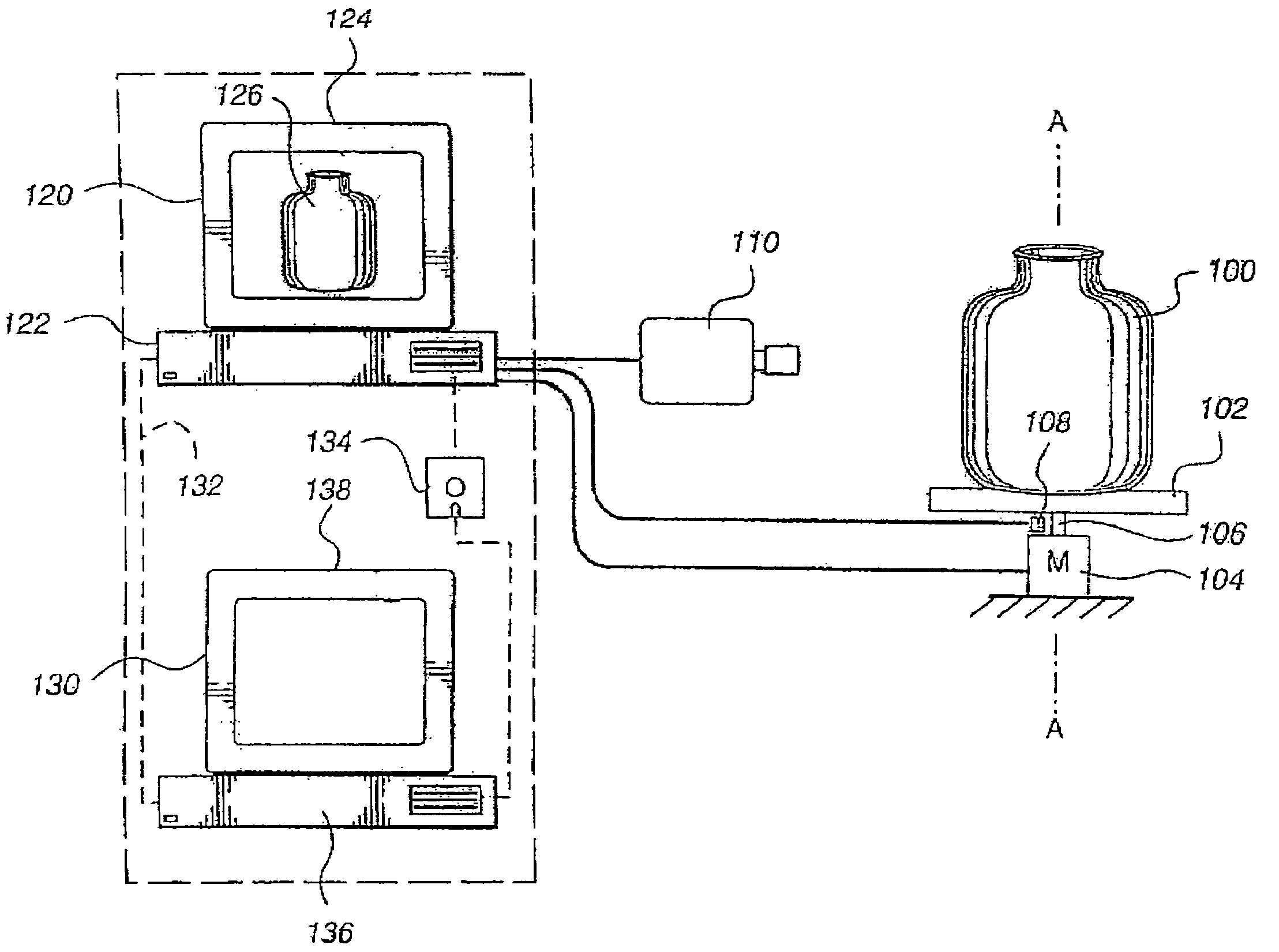
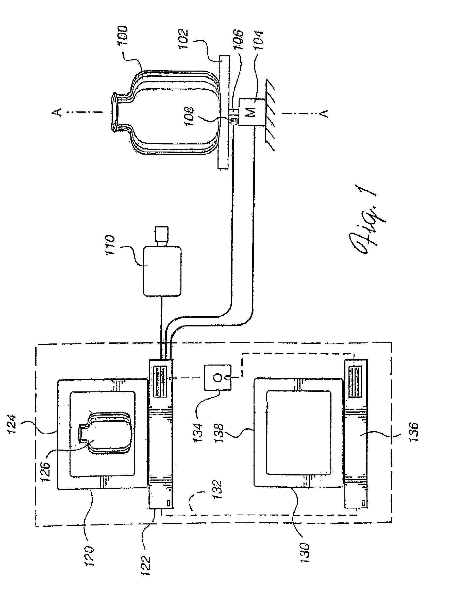
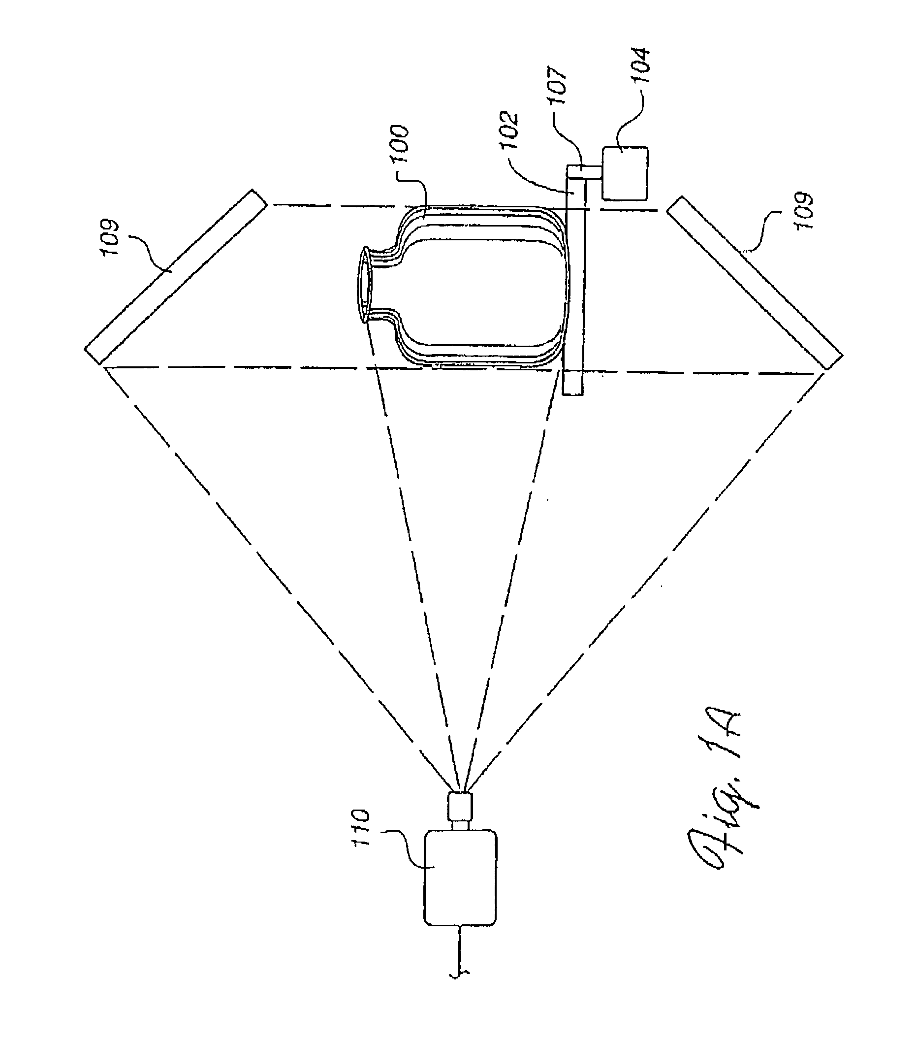
[0042]In FIG. 1, an embodiment of the present invention includes a system for obtaining a series of two dimensional color images of an object and processing those images to obtain a three dimensional model of the surface of the object. An object 100 which is to be digitized is placed on a rotatable platform 102. A motor 104 is provided to drive rotatable platform 102 via a shaft 106. A position encoder 108 detects the angular position of rotatable platform 102 and generates an electrical signal which represents the angular position of rotatable platform 102. An optical detector 110 (e.g. a color video camera) views object 100 and creates a two dimensional color image of object 100.

[0043]As object 100 is rotated by rotatable platform 102, detector 110 captures a series of color images of object 100. Each color image taken at a different time is associated with an angular rotation of object 100 about an axis of rotation, “A” which runs through shaft 106. Information about the angular ...


PUM


Abstract

Apparatus and method for creating 3D imagery of an object using calibration means to transfer data to a reference frame and visibility analysis to determine and resolve occlusion.

Description

REFERENCE TO RELATED APPLICATIONS[0001]This application is a continuation-in-part of U.S. application Ser. No. 09 / 945,133 filed on Aug. 31, 2001, now abandoned which is a continuation of U.S. application Ser. No. 09 / 236,727 filed on Jan. 25, 1999 now U.S. Pat. No. 6,288,385 issued on Sep. 11, 2001 which is a continuation of U.S. application Ser. No. 08 / 738,437 filed on Oct. 25, 1996, now U.S. Pat. No. 5,864,640 issued on Jan. 26, 1999 all of which are incorporated herein by reference.[0002]Appendix A entitled SIGGRAPH 2001 Course: Acquisition and Visualization of Surface Light Fields is attached hereto and made a part hereof by reference.[0003]1. Technical Field[0004]This invention relates generally to optical scanners, and more particularly to optical scanners for providing a digital representation of three dimensional objects.[0005]2. Background Art[0006]Methods for successfully obtaining two dimensional (“2-D”) color image data for objects have been developed. This process is com...

Claims


Application Information

Patent Timeline
IPC IPC(8): H01L27/00G01B11/00G06T7/00H04N13/221
CPCG01B11/00G06T7/0018G06T7/0065H04N13/0221H04N13/0246H04N13/0253G06T2200/08G06T2207/10012H04N13/0055H04N2013/0081H04N13/0239H04N13/0242H04N13/0059G06T7/80G06T7/55H04N13/243H04N13/194H04N13/221H04N13/254H04N13/189H04N13/246H04N13/239
Inventor MUELLER, FREDERICK E.MIRAMONTI, JOHN L.
Owner WAVEWORX
Why Eureka
Try Eureka