Photoelectric sensor

a technology of photoelectric sensor and sensor, applied in the field of photoelectric sensor, can solve the problems of low light utilization efficiency, s/n (signal-to-noise ratio), increased noise, etc., and achieve the effect of preventing detection errors, suppressing light, and improving the quantity of received ligh

Inactive Publication Date: 2006-08-29
KEYENCE
View PDF20 Cites 20 Cited by
  • Summary
  • Abstract
  • Description
  • Claims
  • Application Information

AI Technical Summary

Benefits of technology

[0015]An object of the invention is to provide a photoelectric sensor improved in light-utilizing efficiency and high in detection accuracy.

Problems solved by technology

The related-art photoelectric sensors however have the following problems.
As a result, the level of noise increases, so that S / N (signal-to-noise ratio) deteriorates.
As described above, in the photoelectric sensor in which the sensor head portion and the main body portion are connected to each other by two optical fiber cables, light-utilizing efficiency is low.

Method used


Image

  • Photoelectric sensor
  • Photoelectric sensor
  • Photoelectric sensor

Examples


first embodiment

(First Embodiment)

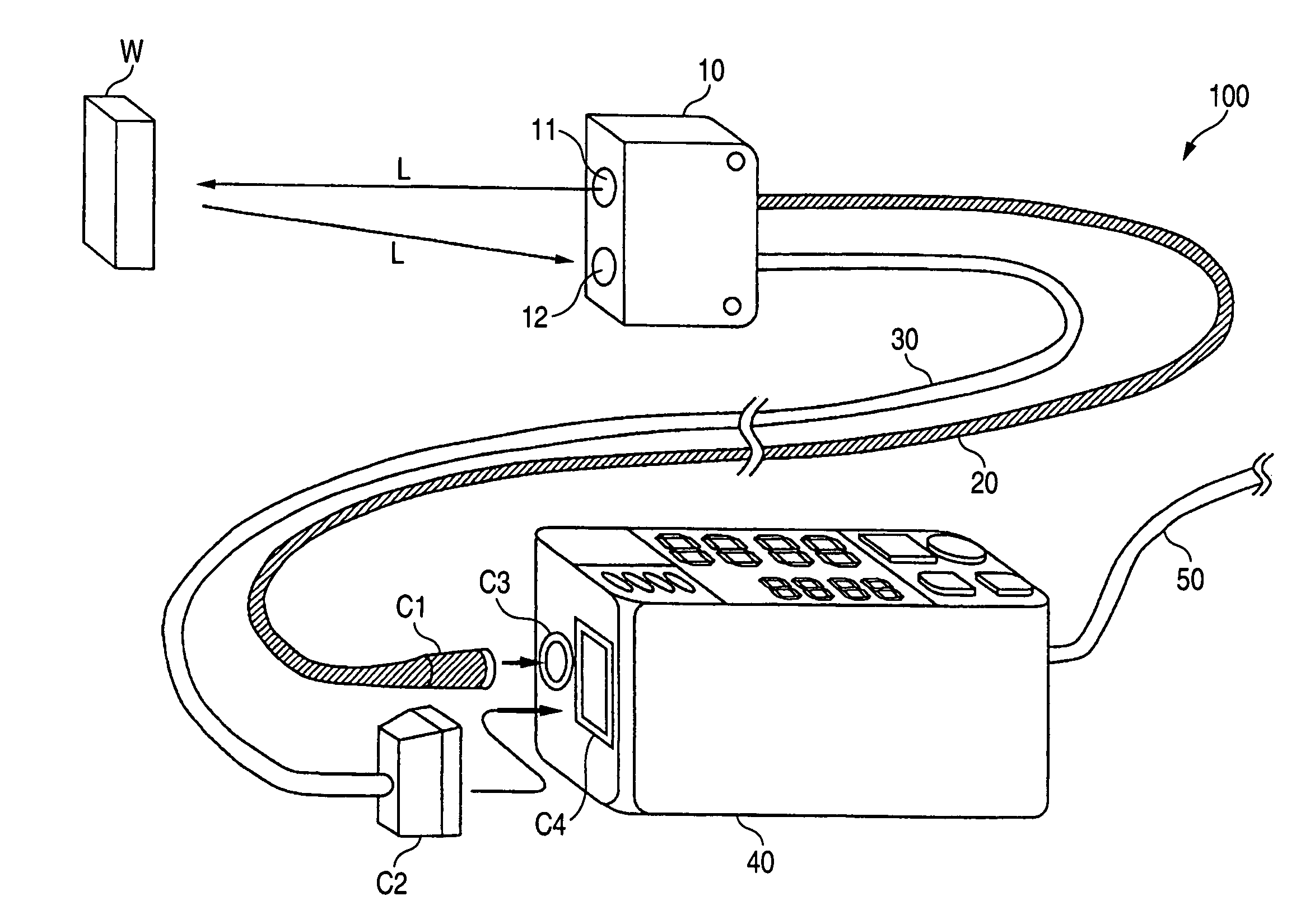
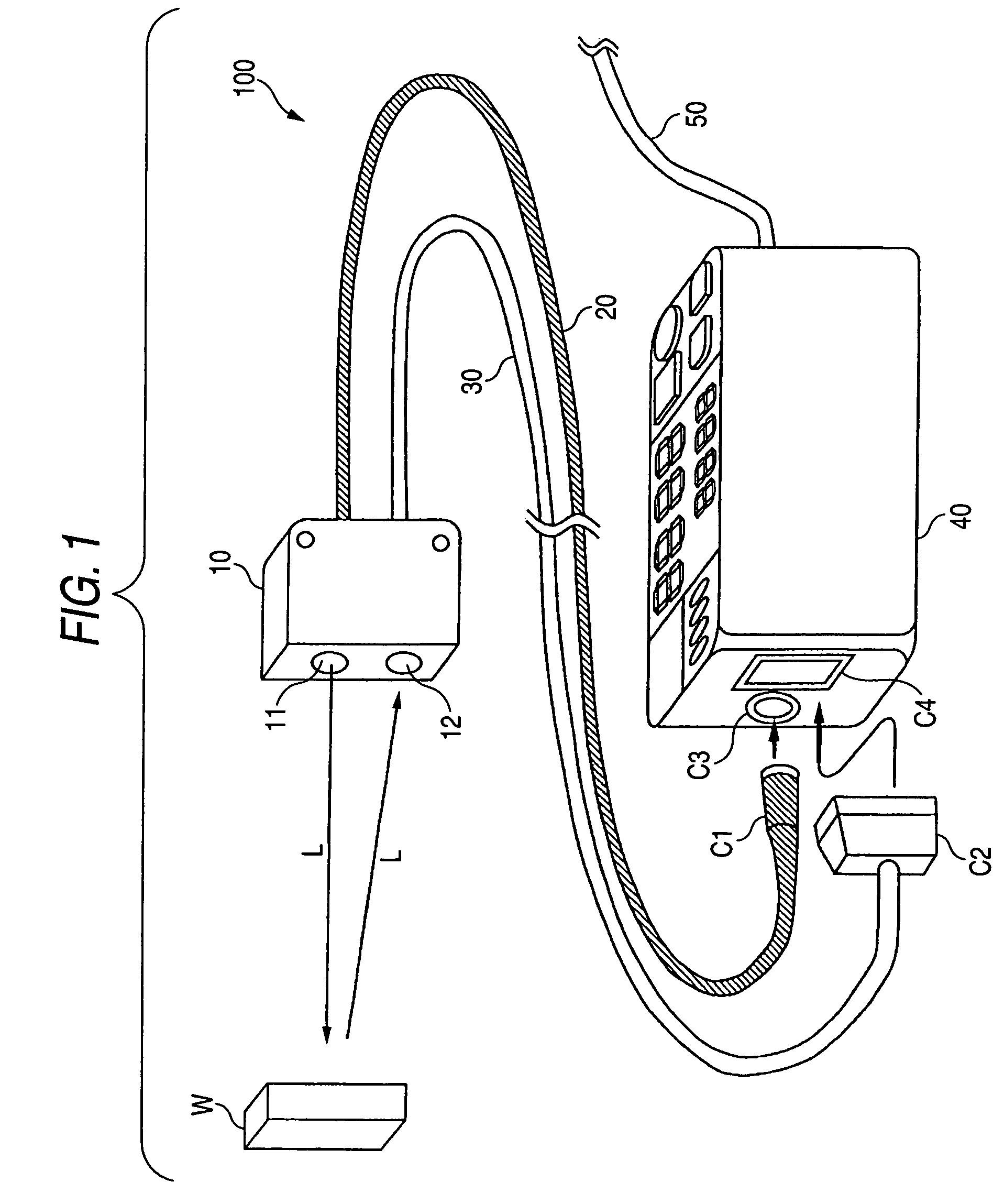
[0081]FIG. 1 is a perspective view showing the external appearance of a photoelectric sensor according to a first embodiment of the invention. The photoelectric sensor according to the first embodiment is a color discrimination sensor for discriminating the color of an object.

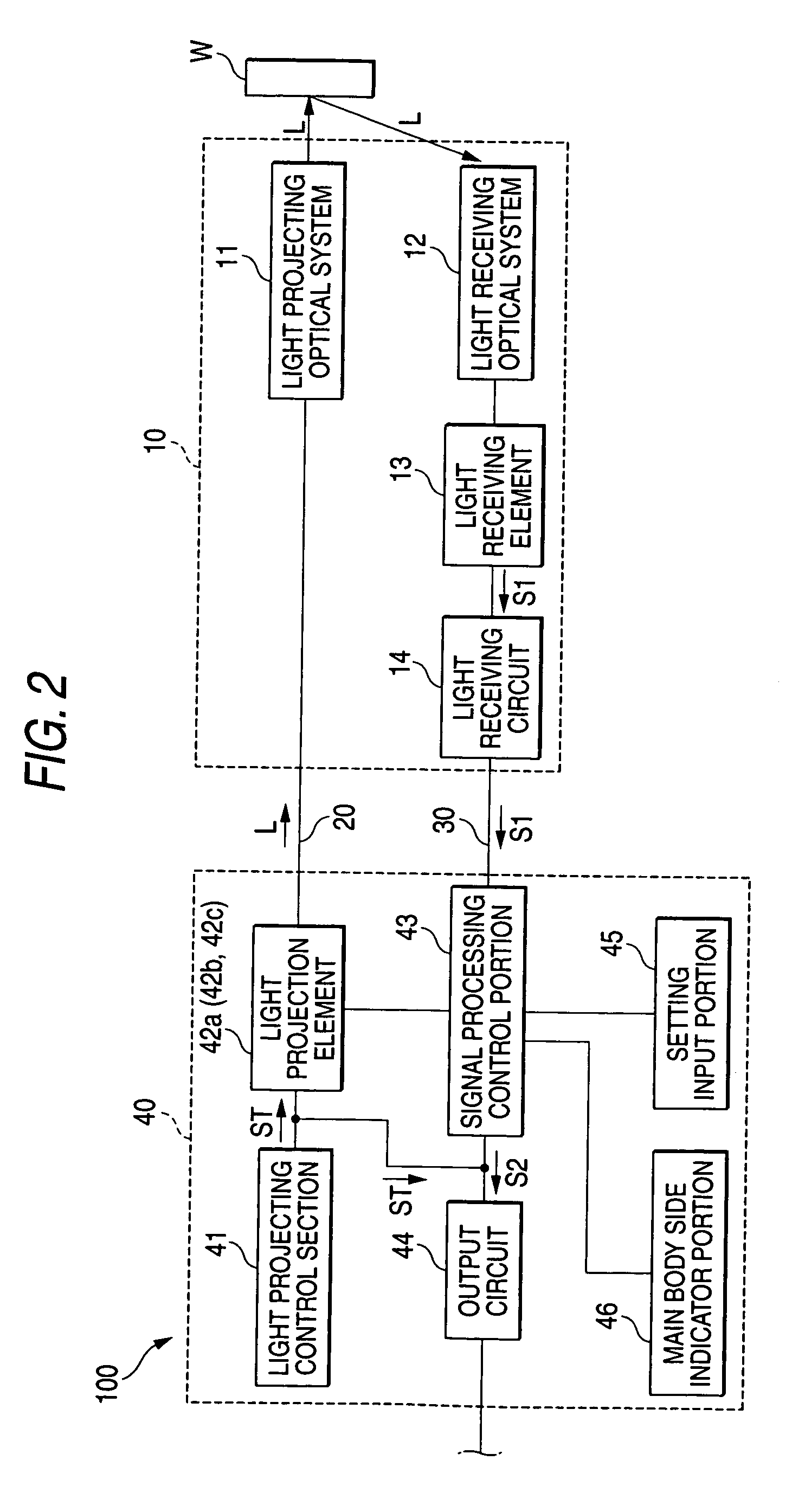
[0082]The photoelectric sensor 100 according to the first embodiment includes a sensor head portion 10, an optical fiber cable 20, an electric wire cable 30, a main body portion 40, and an output cable 50.

[0083]As shown in FIG. 1, a connector C1 of the optical fiber cable 20 extending from the sensor head portion 10 is connected to a connector C3 of the main body portion 40. A connector C2 of the electric wire cable 30 extending from the sensor head portion 10 is connected to a connector C4 of the main body portion 40. The output cable 50 extending from the main body portion 40 is connected to an external apparatus not shown.

[0084]A light-projecting optical system 11 and a light-receiving opti...

second embodiment

(Second Embodiment)

[0139]A photoelectric sensor according to a second embodiment of the invention has the same configuration and operation as those of the photoelectric sensor 100 according to the first embodiment except the following points.

[0140]FIG. 10 is a block diagram showing the internal configuration of the photoelectric sensor according to the second embodiment.

[0141]The photoelectric sensor 200 according to the second embodiment includes an indicator circuit 15, and at least one indicator lamp 16 in addition to the configuration of the photoelectric sensor 100 according to the first embodiment. The indicator circuit 15 and the indicator lamp 16 are provided in the inside of the sensor head portion 10.

[0142]As shown in FIG. 10, the indicator circuit 15 of the sensor head portion 10 is connected to the signal processing control portion 43 of the main body portion 40 by the electric wire cable 30.

[0143]The signal processing control portion 43 of the main body portion 40 trans...

experimental examples

[0254]The present inventor conducted the following experiment to examine the influence of presence of the first and second polarizing plates 111 and 121 (hereafter collectively referred to as “polarizing plates”) and inclination of the object W on the quantity of light incident on the light-receiving element 13 (hereinafter referred to as “total incident light quantity”) and the detected color value. Incidentally, the experiment was conducted on two objects W. One of the objects W is assumed to be an object J1 while the other is assumed to be an object J2. A surface of the object J2 is rougher than a surface of the object J1.

[0255]First, the inventor disposed the object J1 as shown in FIG. 23. The total-incident light quantity and the detected color value were measured, in accordance with the inclination α of the object J1 with reference to a surface WH perpendicular to light L projected from the light-projecting optical system 11, by a photoelectric sensor 100 provided with polariz...


PUM


Abstract

Light emitted from light-projecting elements constituted by LEDs (light-emitting diodes) or the like is transmitted to a light-projecting optical system of a sensor head portion through an optical fiber cable and projected from the light-projecting optical system onto an object. The light projected onto the object is reflected on the object. The reflected light is made incident on a light-receiving optical system. The light incident on the light-receiving optical system is led to a light-receiving element. The light-receiving element detects the incident light and generates a light-receiving signal based on the quantity of the detected light. The light-receiving signal generated by the light-receiving element is transmitted to a signal processing control portion of a main body portion through a light-receiving circuit and an electric wire cable.

Description

[0001]This application claims foreign priorities based on Japanese patent application JP2003-348429, filed on Oct. 7, 2003 and Japanese patent application JP 2004-079135, filed on Mar. 18, 2004, the contents of which are incorporated herein by reference in its entirety.BACKGROUND OF THE INVENTION[0002]1. Field of the Invention[0003]The present invention relates to a photoelectric sensor provided with light-projecting elements and a light-receiving element.[0004]2. Description of the Related Art[0005]A photoelectric sensor is used for detecting the presence of an object in a detection region, the position of the object, the color of the object, etc. by means of projecting light on the detection region and receiving the reflected or transmitted light from the object.[0006]In a separate type photoelectric sensor, a sensor head portion for projecting light and receiving light and a main body portion for processing various signals are separated from each other.[0007]As a related-art sepa...

Claims


Application Information

Patent Timeline
Patent Type & Authority Patents(United States)
IPC IPC(8): H01L31/00G01J1/02G01J1/42G01J3/50G01V8/16H01H35/00H03K17/78
CPCG01V8/16
Inventor YAMAGUCHI, AKIJIASADA, SHINYATSUKIGI, SHINICHI
Owner KEYENCE
Why Eureka
Try Eureka