
Flexographic rotary platen printing press

a printing press and rotary plate technology, applied in printing presses, rotary letterpress machines, printing, etc., can solve the problems of inability to maintain an even print, indicia of printing, and inability to accurately carry out printing processes, etc., to achieve accurate printing.

Inactive Publication Date: 2006-09-05
GREYDON
View PDF24 Cites 9 Cited by
  • Summary
  • Abstract
  • Description
  • Claims
  • Application Information

AI Technical Summary

Benefits of technology

[0013]As is known, the inking process can also be carried out by conventional inking systems including the use of an anilox roller and the inking system may utilize a closed doctor blade type utilizing a laser engraved ceramic coated anilox roller mounted in a stationary position off to the side of the web and fed with ink by an inverted bottle cartridge of pigmented ink. In the inking system, the anilox roller is driven, preferably by a stepper motor, and that stepper motor is coordinated with a stepper motor that drives the print drum during the inking process such that the two motors are synchronized electronically to assure that the surface speeds of the anilox roller and the print plate on the print drum match without the need to link the two motors or drives together with gears. As will be noted, the various rotating motive means will be described herein with the preferred means, that is by use of stepper motors, however, it will be seen that other motive means, including servo motors, could be used in carrying out the present invention and still be within the inventive concept. Of importance, however, is that with the use of speed controllable motors, the coordination of the speeds between the anilox roller and the print drum can be carried out electronically and thus, without the need for any gearing system to provide that coordination of such speeds.
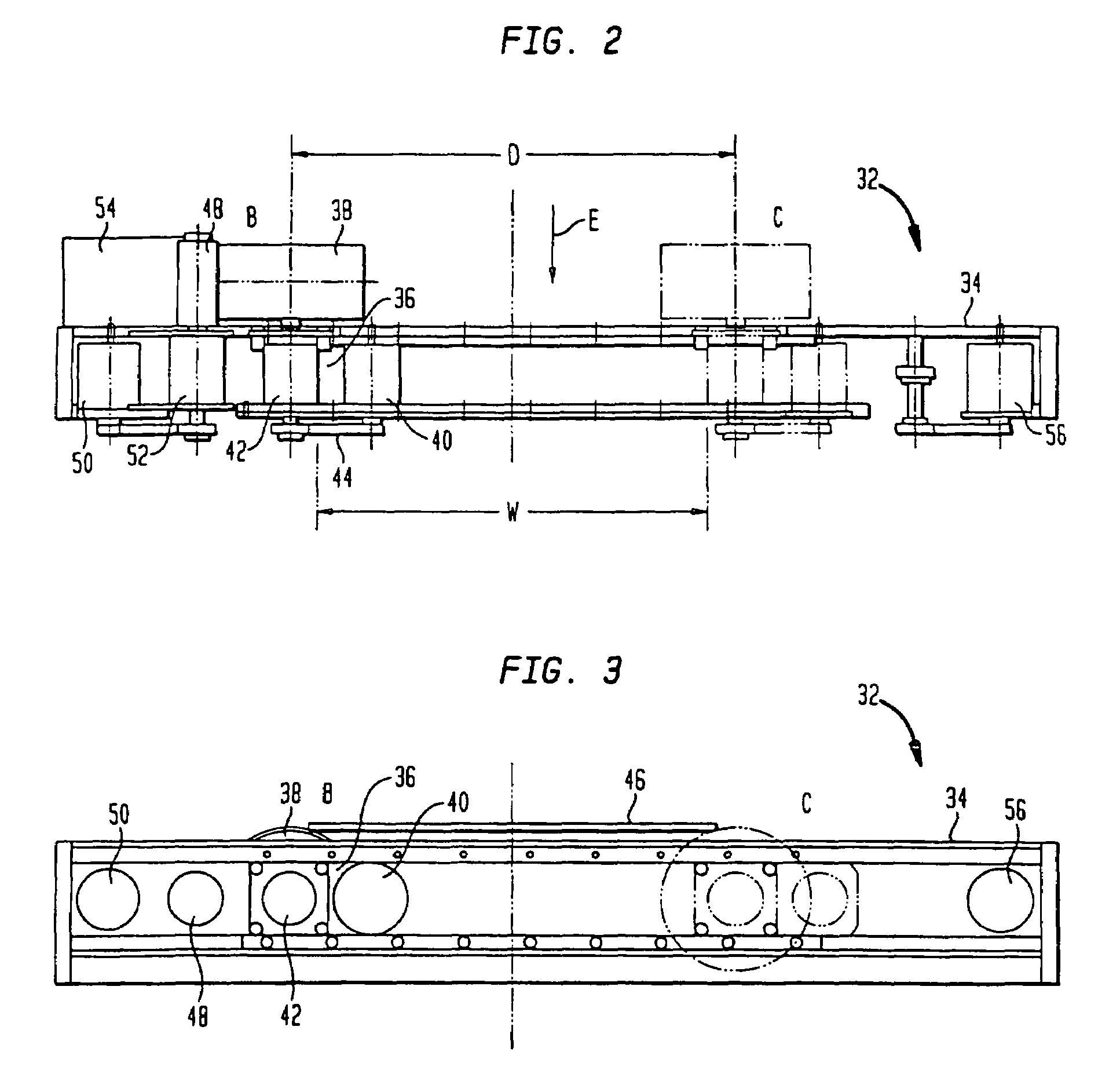
[0016]At this step, the speed of the rotation of the print drum is controlled to be coordinated with the linear speed of the print drum as it moves transversely across the web to print the desired indicia on the web at a precise registration. The web, being sandwiched between the print drum and a flat platen, is therefore at a standstill and the printing process can be carried out accurately and the contact between the printing plate and the flat platen is a line contact. The print drum continues its progress, moved by the linear drive motor, from the first or home position fully across the web to a remote position past the web where its motion is terminated and printing has been accomplished. Upon that completion of the print step, the print drum will lift away from the platen and return to the home position juxtaposed to the inking system ready to carry out the process again.
[0017]As such, the entire process for a print cycle can be carried out by means of three stepper motors; an anilox motor to rotate the anilox roller, a linear drive motor to move the print drum in a linear path across the web and a print drum motor that rotates the print drum. All coordination of the motors can be readily be accomplished electronically by a microprocessor based system.

Problems solved by technology

While that Type of system allows good registration of the indicia to be printed onto the web, there is an inherent fault in that it is extremely difficult to maintain an even print over such as large area, that is, the printing plate must be precisely planar and parallel to the plane of the platen or the eventual printed indicia is uneven, and exhibits a non-uniform pattern.
Again, however, the aforedescribed system has certain limitations as the moving web must be carefully aligned with the platen and the printing roller and thus is carried through a large number of idler rollers that guide the web to the proper position for printing, including an impression roller that requires the web to form a complete S configuration for correct alignment, registration and for providing the proper tension at all times on the moving web.
Each roller, therefore, changes the direction of the web as it is moving through the printing press and each roller and change of direction also induces a stress on the web and can cause a stretching of the web and result in the final printed indicia being blurred.
Accordingly, while the use of a multiplicity of tensioning and other rollers is necessary in the operation of the aforedescribed press to carry out printing on the fly, there is also a downside, that is, while the rollers are essential in the overall control of the web tension and control of the web orientation, the use of so many rollers generally creates many changes in direction of the web and also introduces stresses in the web that are undesirable.
The problem is aggravated with the use of multicolor printing where different colors are used since those different colors are printed on to the web serially, that is, after the printing of one color on to the web, the web, still moving at a high speed, progresses to a further printing cycle where the next color is applied to the web and so on.
Obviously then, with a multi color printing, there are two, three of additional sets of rollers through which the web must travel and, again, each additional set of rollers can cause stress, stretch the web and make the registration of the subsequent colors extremely difficult.
Too, with the multiple color printing presses, there is no room to insert dryers intermediate the color printing steps and thus the system is limited to materials having some porosity of the web material to allow the ink to dry before passing through a later printing stage with a different color.
Accordingly, the use of such a multi-color rotating drum printing press is inappropriate for the other non-porous materials of webs, such as polyethylene, nylon, or polypropylene.

Method used


Image

  • Flexographic rotary platen printing press
  • Flexographic rotary platen printing press
  • Flexographic rotary platen printing press

Examples


Embodiment Construction

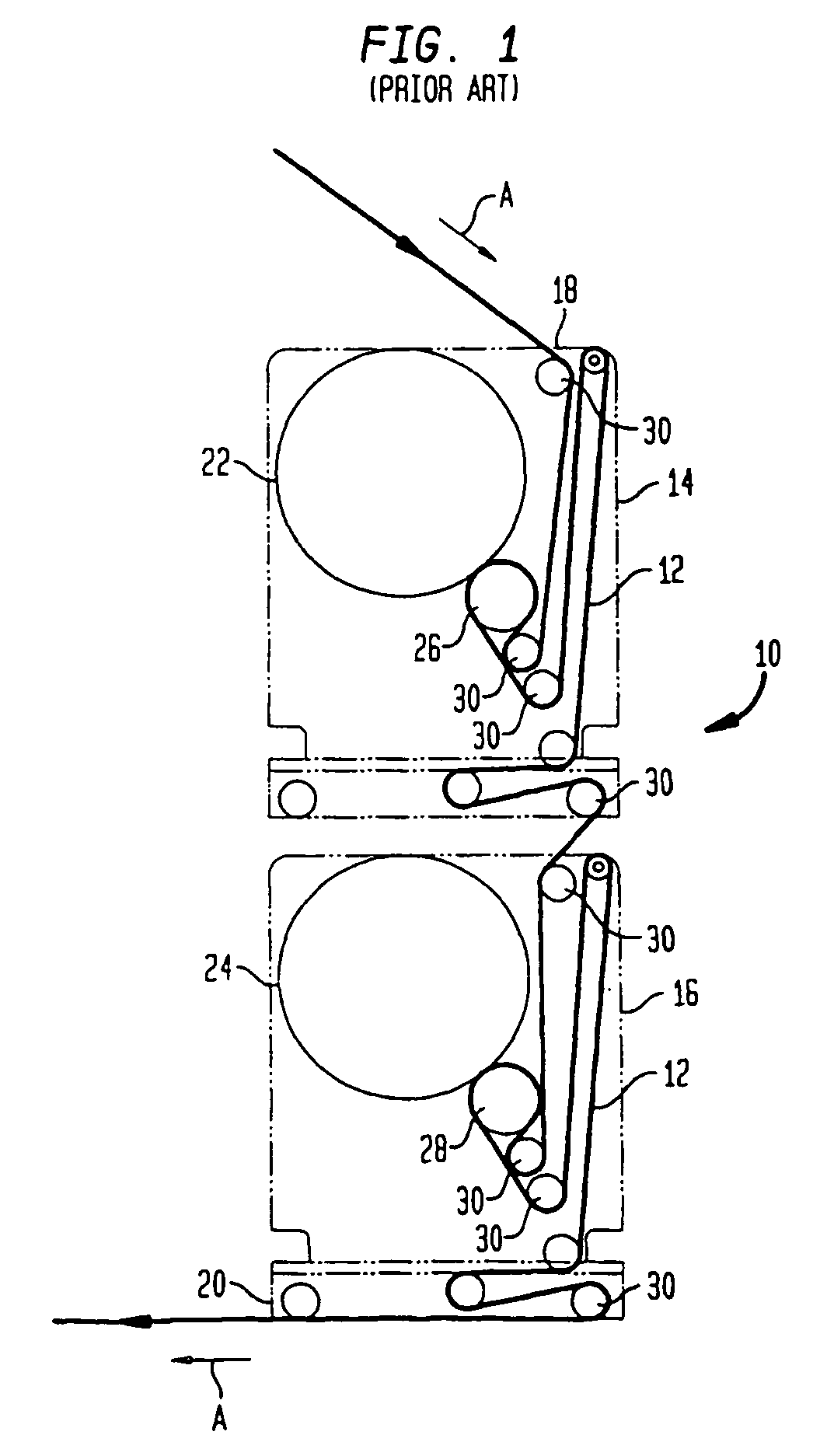
[0026]Referring now to FIG. 1, there is shown a schematic view of a typical prior art flexographic printing press system 10 currently used to carry out the printing of multi-colors onto a web 12 of flexible material. As can be seen, in order to print more than one color, the flexographic printing press system 10, of necessity, requires, basically, separate printing presses, that is, there is a first printing press 14 for printing indicia of one color onto the web 14 and a second printing press 16 to print the second color onto that web 12. Obviously, while the FIG. 1 illustrates a printing system 10 utilizing two colors, there may be additional colors that can be printed on to the web 12 with the consequent equal number of additional printing presses that print those additional colors onto the web 12.

[0027]In FIG. 1, however, it can be seen that the web 12 progresses through a serpentine path as it passes from the entrance 18 to the first printing press 14 to the exit 20 of the seco...


PUM


Abstract

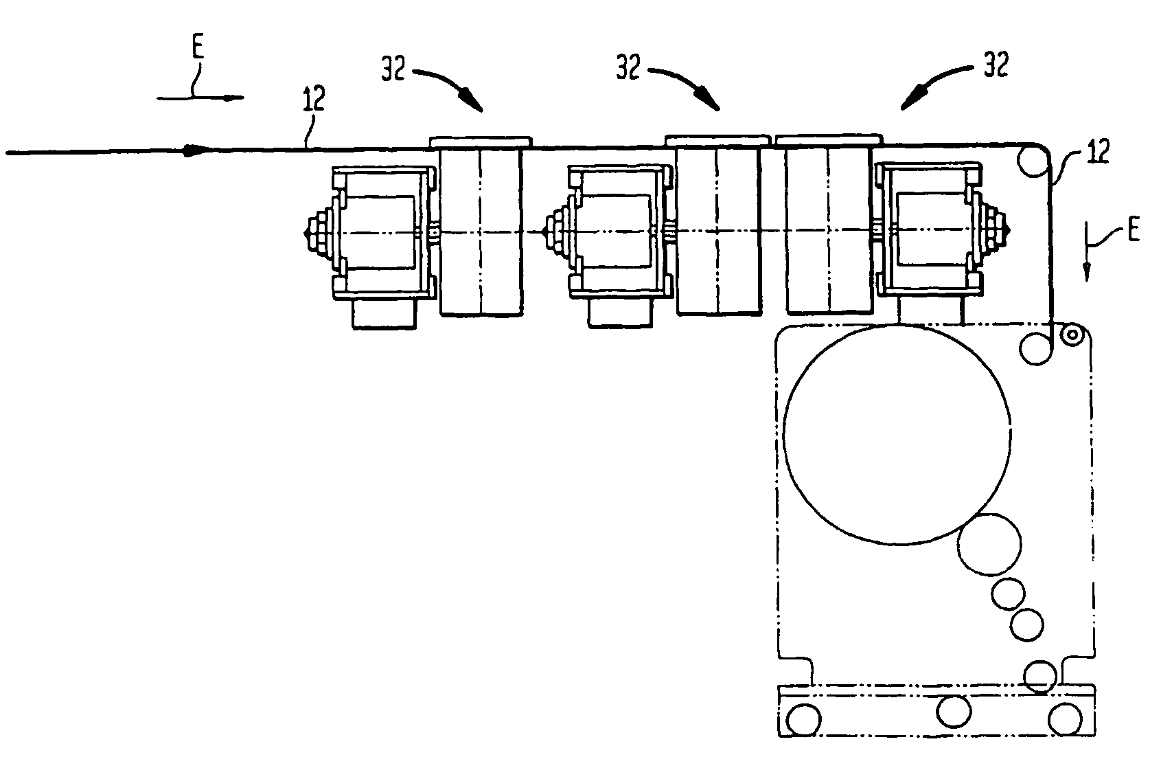
A flexographic rotary platen printing press for printing indicia on a web of flexible material moving along a longitudinal axis. The flexographic rotary platen printing press includes a print drum assembly that is affixed to a trolley that is moveable in a linear direction across the web generally transverse to the direction of the web movement. When the web is stopped, the print drum is caused to roll across the web that is sandwiched between the print drum and a flat, planar platen to print indicia onto the web in a line contact. A linear drive system causes the movement of the print drum assembly. The speed of the transverse movement is electronically coordinated to the speed of the rotation of the print drum as it moves across the web to carry out the printing operation. A multi-color printing process is created by serially positioning two or more flexographic presses without the use of a large number of idler rollers or changes of direction in the path of the web as it moves from one flexographic printing press to a subsequent flexographic printing press.

Description

CROSS REFERENCE TO RELATED APPLICATIONS[0001]This application is a continuation of patent application Ser. No. 10 / 662,677 filed Sep. 15, 2003, now U.S. Pat. No. 6,834,588 B1, issued Dec. 28, 2004, which is a division of U.S. application Ser. No. 09 / 707,049, filed Nov. 6, 2000, now U.S. Pat. No. 6,644,185 B1, issued Nov. 11, 2003.BACKGROUND OF THE INVENTION[0002]The present invention relates to a flexographic rotary platen printing press utilized for printing indicia onto a flexible web, and, more particularly, to a flexographic rotary platen press having a printing system that makes the printing process easier and with accurate indexing of multiple printing colors.[0003]The use of various printing presses are, of course, well know for their use in providing the printing of a web of flexible material, such as plastic material used in packaging industry for various products. In such systems for printing and in general, the packaging machine, or host machine, actually pulls the web thr...

Claims


Application Information

Patent Timeline
IPC IPC(8): B41F33/00
CPCB41F3/04B41P2200/12
Inventor ROCHON, GREGORY P.FICKES, WAYNE F.GLATFELTER, THOMAS
Owner GREYDON
Learn More