
Containment system for continuous flow hydrolyzers

a technology of continuous flow and hydrolyzer, which is applied in the field of hydrolyzers, can solve the problems of practical upper and lower limits of pressure and temperature, and achieve the effect of increasing the temperature and pressure of the hydrolyzer and accelerating the chemical reaction

Inactive Publication Date: 2006-09-05
BOULDIN CORP
View PDF11 Cites 14 Cited by
  • Summary
  • Abstract
  • Description
  • Claims
  • Application Information

AI Technical Summary

Benefits of technology

[0018]Of course, the process of the present invention could be carried out at other temperature and pressure ranges, but the associated time for completion of the inventive process at these other temperature and pressures will vary significantly. That is, the greater the temperature and pressure in the hydrolyzer, the faster the chemical reactions occur. However, a practical upper and lower limit to pressure and temperature exists.
[0019]The pressure and temperature, in conjunction with the composition of the MSW, acts as the catalyst to speed the chemical reaction of decomposition of the MSW within the vessel. This high temperature and pressure environment causes the MSW to rapidly decompose into its basic constituent elements, and allows them to recombine or remain in their organic cellulose form, and it kills bacteria once living within the MSW.

Problems solved by technology

However, a practical upper and lower limit to pressure and temperature exists.

Method used


Image

  • Containment system for continuous flow hydrolyzers
  • Containment system for continuous flow hydrolyzers
  • Containment system for continuous flow hydrolyzers

Examples


Embodiment Construction

)

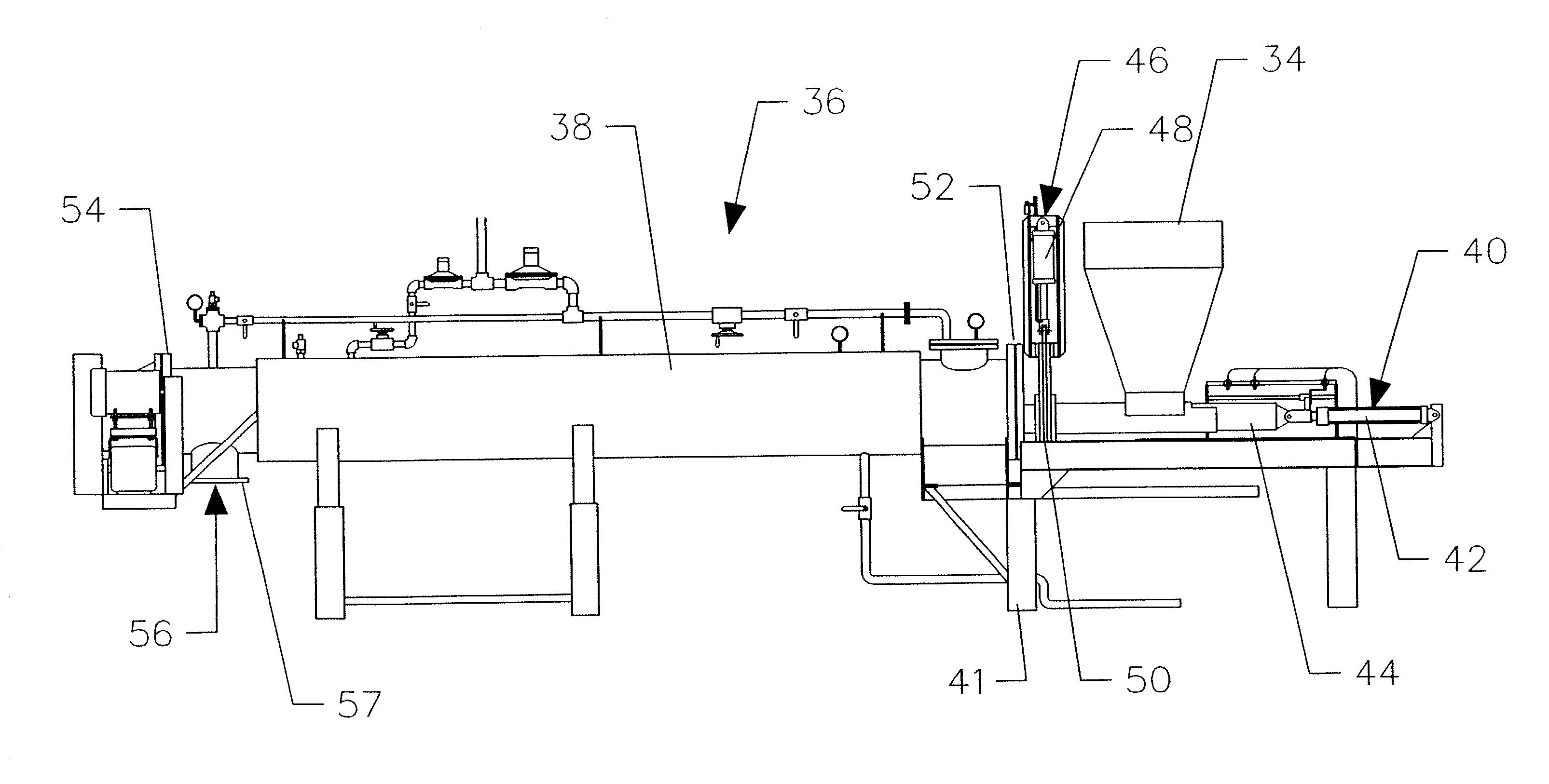
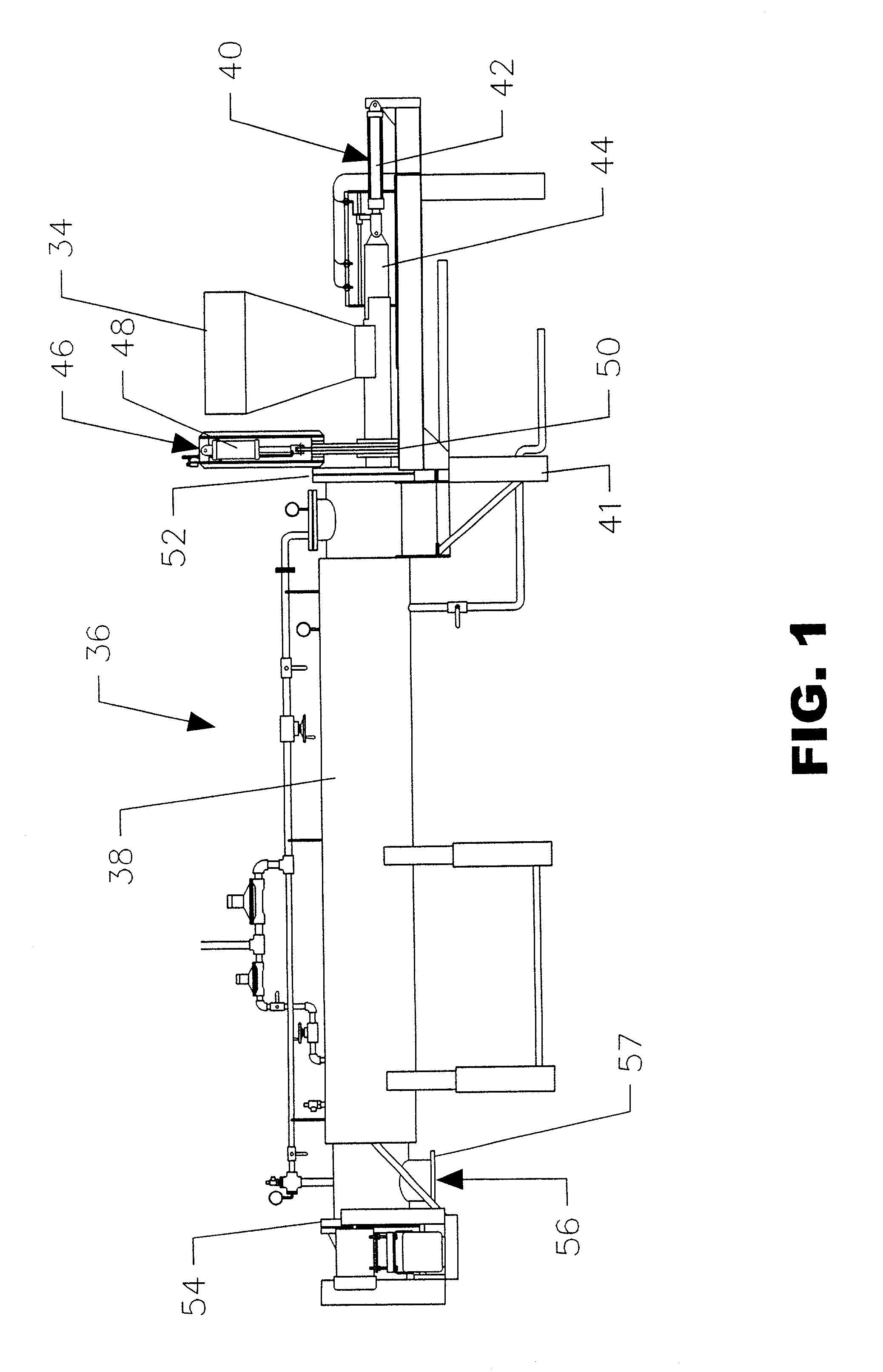
[0037]With reference to FIG. 1, a hydrolyzer is designated generally by the reference numeral 36. Hydrolyzer 36 includes a cylindrical pressure vessel 38, and a material injection assembly designated generally by the reference numeral 40. Platform 41 elevates and supports the various components above the ground.

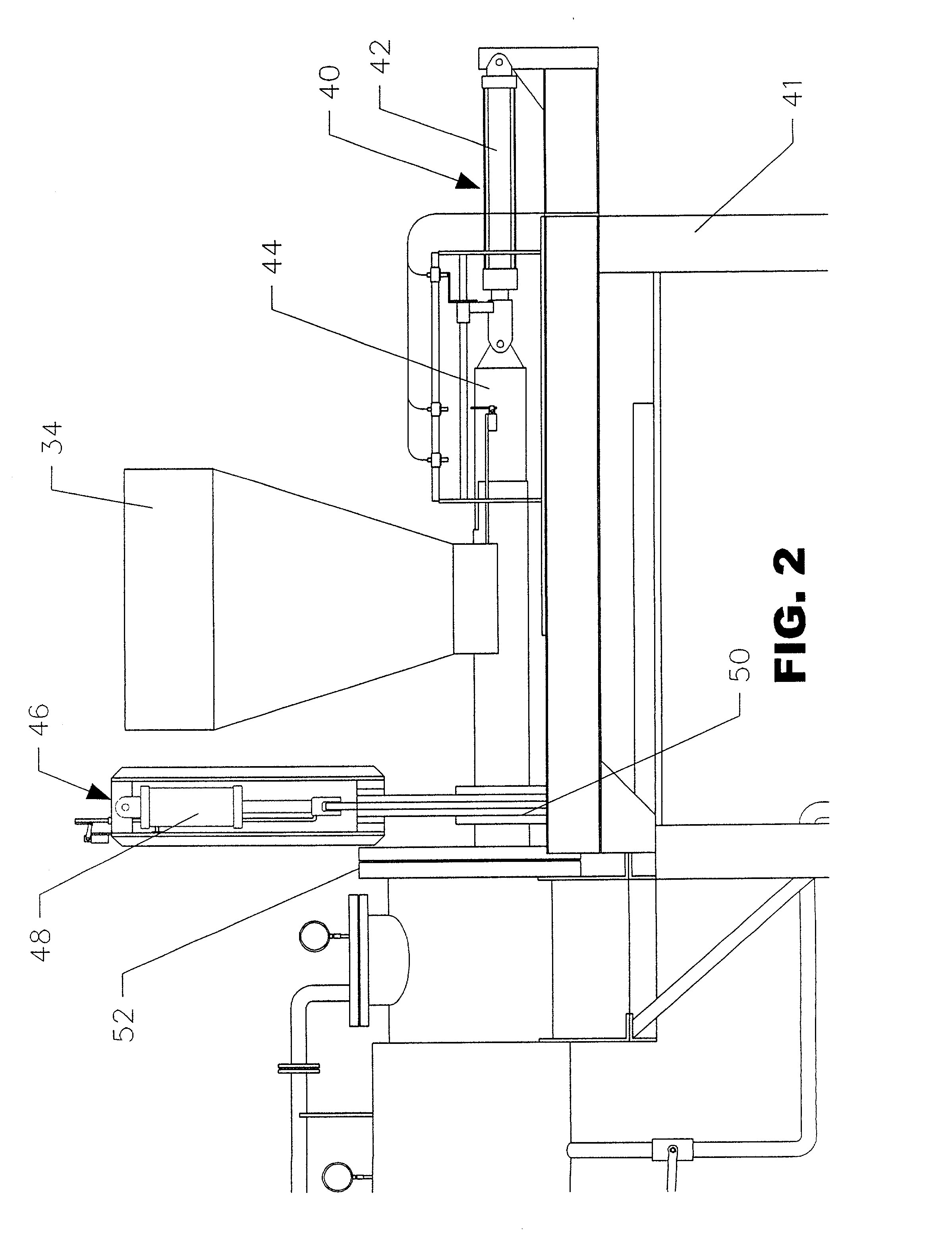
[0038]With reference to FIGS. 1–3, the material injection assembly 40 further includes a pneumatic or hydraulic cylinder 42 operably connected to a ram 44. An infeed regulator gate assembly is also provided and is designated generally by the reference numeral 46. The gate assembly 46 includes a vertically (as shown but also be at any angle) oriented pneumatic or hydraulic cylinder 48 operably connected to a sliding gate assembly 50 which opens and closes an internal passageway into the hydrolyzer 38 at an inlet end 52 which is opposite the exit end 54 having exit port 56.

[0039]FIGS. 4A–4E are provided to illustrate the operation of the material injection assembly 40 during u...


PUM

PropertyMeasurementUnit
temperatureaaaaaaaaaa
timeaaaaaaaaaa
combustibleaaaaaaaaaa

Abstract

A material handling system for a hydrolyzer comprises a material injection assembly having a ram; a sleeve in which the ram reciprocates during use; a gate plate operable from between an open position, wherein a plug of municipal solid waste may exit the sleeve, and a closed position; and a material exit assembly. The material exit assembly comprises a processed material handling apparatus including a processed material compaction chamber; and a plunger assembly attached to the compaction chamber and further including a working cylinder having a cylinder shaft and a ram operably connected to the shaft enabling the ram to compact the processed material within the compaction chamber upon actuation of the cylinder and the extension of the shaft therefrom.

Description

BACKGROUND OF THE INVENTION[0001]1. Field of the Invention[0002]The present invention relates generally to hydrolyzers for processing organic material (i.e., rendering) and further relates generally to the apparatuses used for the rendering of animal carcasses or parts thereof into useful end products such as bone or feather meal. In addition, the present invention has proven particularly useful for processing (i.e., rendering) municipal solid waste even though the material characteristics of municipal solid waste and the rendering of animal carcass parts is distinctly different.[0003]The present invention is primarily directed to a pressure vessel apparatus in the general nature of a hydrolyzer used for the reduction, decomposition, destruction and / or conversion (hereinafter “rendering”) of organic wastes generated during meat and poultry production for human consumption.[0004]The present invention also relates generally to an innovative method of handling municipal solid waste dis...

Claims


Application Information

Patent Timeline
Patent Type & Authority Patents(United States)
IPC IPC(8): B29C43/34B09B3/00B29C48/92
CPCB09B3/00B29C47/92B09B3/0083B09B3/0025B09B3/40B09B3/20
Inventor BOULDIN, FLOYD E.
Owner BOULDIN CORP
Learn More