Flank superabrasive machining

Active Publication Date: 2006-09-05
RAYTHEON TECH CORP
View PDF12 Cites 24 Cited by
  • Summary
  • Abstract
  • Description
  • Claims
  • Application Information

AI Technical Summary

Benefits of technology

[0004]Accordingly, it is an object of the present invention to provide an improved tool f

Problems solved by technology

These techniques however are slow and the tools used to perform them do not have a particularly long life especially, in hardened alloyed materials such as nickel alloys.
The cutting forces produced during the milling operation result in high loads on the workpie

Method used


Image

  • Flank superabrasive machining
  • Flank superabrasive machining

Examples


Embodiment Construction

)

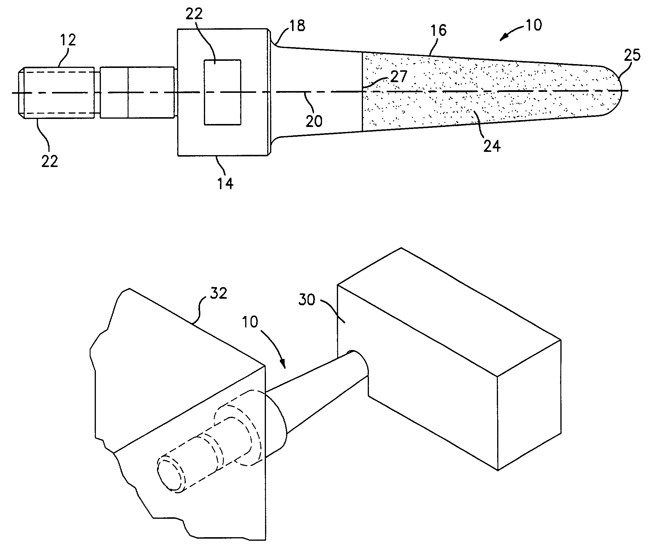
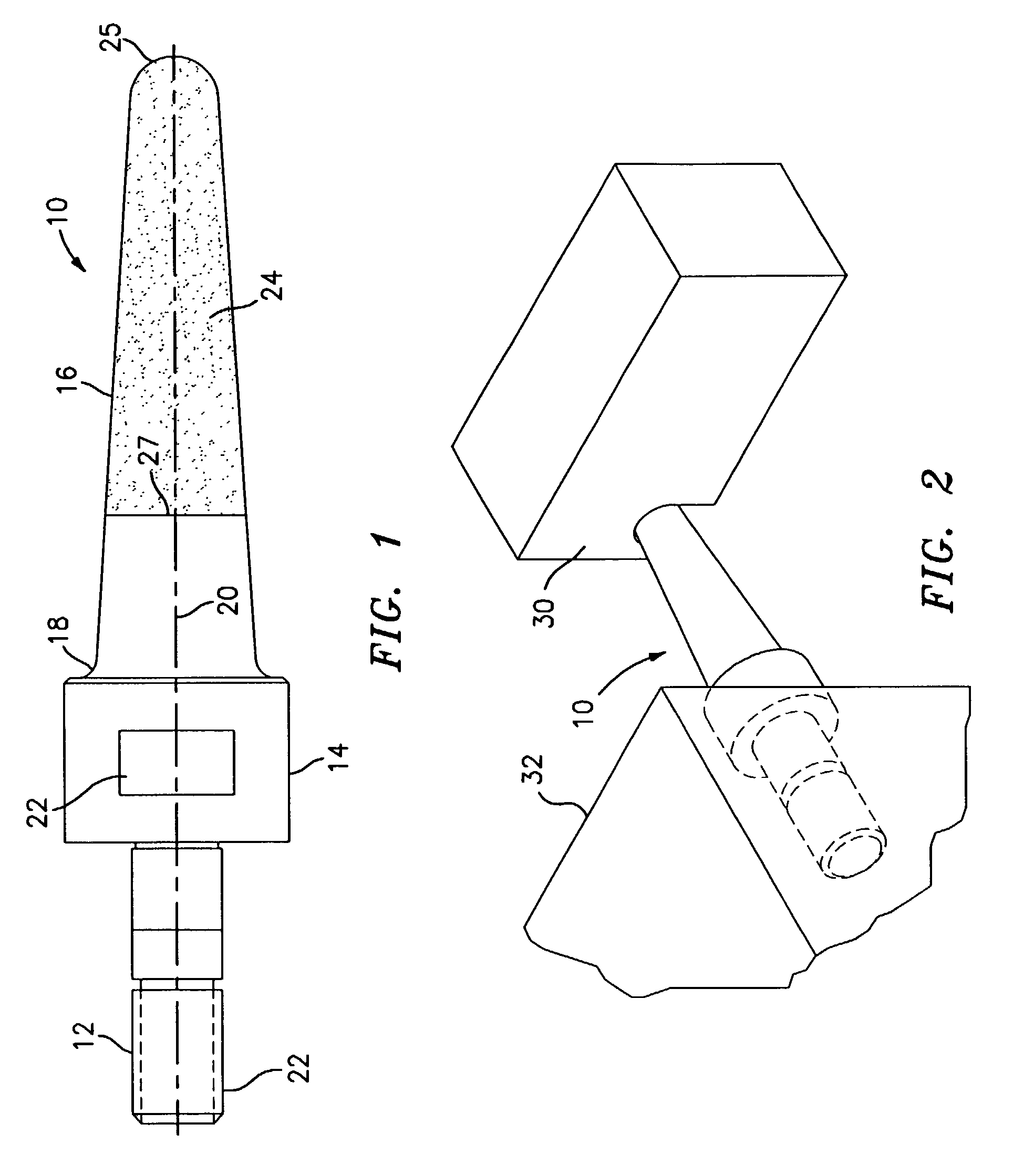
[0013]Referring now to the drawings, FIG. 1 illustrates a flank superabrasive machining tool or quill 10 for machining complex airfoil shapes into a substrate material selected from the group of nickel alloys, titanium alloys, and stainless steel. The tool 10 has a shaft portion 12, an enlarged head portion 14, and a tapered grinding portion 16. The tapered grinding portion 16 is joined to the head portion 14 by a fillet portion 18.

[0014]The shaft portion 12 of the tool 10 is intended to fit into a grinding spindle of a milling machine. The tool 10 has a longitudinal axis 20 about which it is rotated. The shaft portion 12 and the head portion 14 are each provided with a plurality of flat portions 22 for accommodating a wrench.

[0015]The tool 10 may be formed from any suitable tool material known in the art such as a steel material.

[0016]The grinding portion 16 has thereon a layer of grit material 24 selected from the group consisting of diamonds and cubic boron nitride. The grit mat...


PUM

PropertyMeasurementUnit
Sizeaaaaaaaaaa

Abstract

The present invention relates to a quill to be used to superabrasively machine complex shapes, such as airfoil shapes, into a substrate. The quill has a shaft portion, an enlarged head portion adjacent the shaft portion, and a tapered grinding portion adjacent the enlarged head portion. The tapered grinding portion has a layer of grit material selected from the group consisting of diamonds and cubic boron nitride thereon. In a preferred embodiment, the quill is a vitrified or plated cubic boron nitride quill on the grinding portion. A method of using the tool is also disclosed.

Description

BACKGROUND OF THE INVENTION[0001]The present invention relates to a tool and a method for machining complex airfoil shapes in materials such as nickel or titanium alloys.[0002]In the past, airfoil shapes have been machined using a variety of different techniques. These techniques included flank milling, electro-chemical machining (ECM), and conventional point milling. These techniques however are slow and the tools used to perform them do not have a particularly long life especially, in hardened alloyed materials such as nickel alloys. The cutting forces produced during the milling operation result in high loads on the workpiece which can result in airfoil deflection and chatter that results in poor surface finish. It is also difficult using these techniques to produce surface finishes that meet part requirements without additional processing such as hand polishing or media finishings.[0003]Thus, there is a need for an improved tool and an improved method for machining complex airfo...

Claims


Application Information

Patent Timeline
IPC IPC(8): B24B1/00B24D3/10B24B19/14B24D3/00B24D3/06B24D3/14B24D7/18
CPCB24D7/18B24B19/14B24D3/10
Inventor SCHWARTZ, BRIAN J.VAILLETTE, BERNARD D.WU, CHUNG Y.COLACINO, GENNARO J.PACKMAN, ALLAN B.
Owner RAYTHEON TECH CORP
Why Eureka
Try Eureka