Single lens 3D camera

Inactive Publication Date: 2006-09-05
MITSUBISHI ELECTRIC RES LAB INC
View PDF2 Cites 38 Cited by
  • Summary
  • Abstract
  • Description
  • Claims
  • Application Information

AI Technical Summary

Benefits of technology

[0029]Although these methods can be worked alone, e.g., the textured range image produced by the interaction method can be converted to 3D models by reconstruction methods that use other means to compute distances, the combination of the methods provides a means for generating detailed 3D models that is cost-effective, (e.g., by using inexpensive digital cameras and significantly reducing labor), practical, (e.g., cameras can go many places range scanners cannot), approachable, (e.g., cameras and 2D editors are simple to use, while range scanners and 3D modelers are not), robust (e.g., hole-free, water-tight models are produced), and efficient (e.g., model generation takes seconds on a desktop machine).
[0030]Therefore, the inven

Problems solved by technology

However, there are times when low-resolution models are insufficient.
However, generating models with high-resolution geometry is a difficult and time-consuming task.
It is often very hard to recreate the complexity and variety of geometric texture that occurs in nature.
High-resolution range scanners, such as Cyberware 3030, provide means for capturing existing geometry but high-resolution scanners are expensive

Method used


Image

  • Single lens 3D camera
  • Single lens 3D camera
  • Single lens 3D camera

Examples


Embodiment Construction

Projected Distances

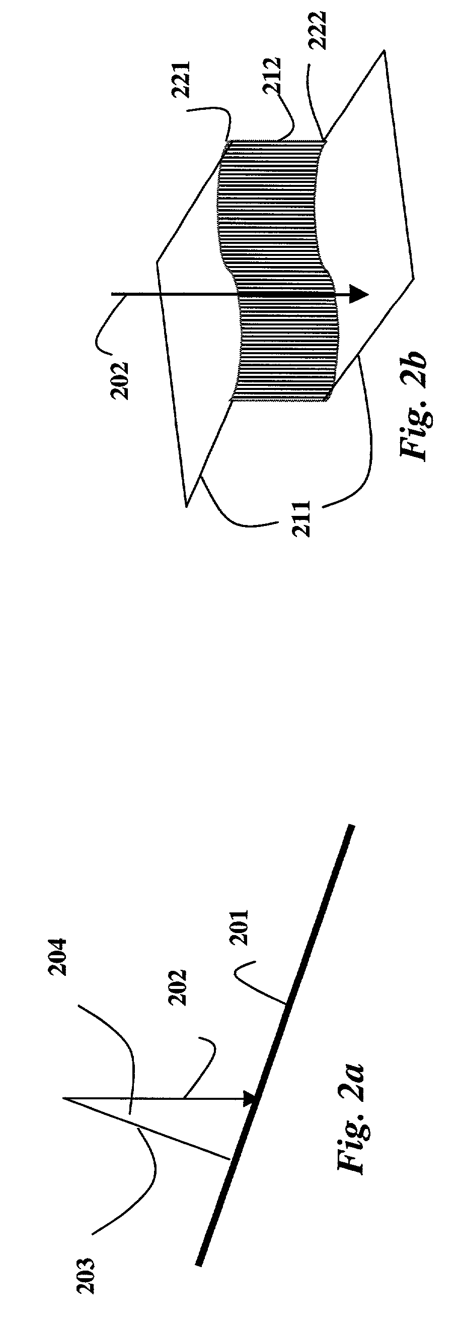
[0042]Two-dimensional (2D) range images provide a 2D grid of line-of-sight distances from a scanner to an object. A line-of-sight distance is measured along a viewing ray from the scanner to the object. In the following description, we assume that each distance value in the range image represents a perpendicular projected distance, where the distance is measured along a ray from the scanner to the object that is perpendicular to the plane of the scanner, also see U.S. Pat. No. 6,262,738 issued to Gibson, et al. on Jul. 17, 2001, “Method for estimating volumetric distance maps from 2D depth images,” incorporated herein by reference, for further details on this problem.

[0043]Scanning systems do not always provide projected distances but conversion to this form can be straightforward. As an example, laser striping systems “fan” a laser beam into a plane of laser light so that each scan line of the range image samples line-of-sight distances along rays radiating from ...


PUM


Abstract

A camera generates a textured range image. The camera includes a single lens, and a flash substantially co-located with the lens. The camera acquires a first image of a scene from a point of view with ambient light, and a second image of the scene from the point of view with direct light of the flash. The first image and the seconds image are then combined by a divider to generate the textured range image.

Description

FIELD OF THE INVENTION[0001]The invention relates generally to cameras, and more particularly to 3D cameras.BACKGROUND OF THE INVENTION[0002]In computer graphics, it is often desired to minimize the amount of geometry in a model of a scene or an object to enable efficient rendering of the model. Several effective approaches have been developed to add visual detail to low-resolution models during rendering, such as texture mapping and bump mapping, see Apodaca et al., “Advanced Renderman,” Morgan Kaufmann, ISBN 1558606181, 2000.[0003]However, there are times when low-resolution models are insufficient. For example, high-end production studios often require models with detailed explicit geometry for physical simulation, e.g., deformation and collision detection. In addition, these studios often employ sophisticated illumination that requires models with high-resolution geometry.[0004]Displacement mapping can be applied to the low-resolution geometry of an underlying model to provide c...

Claims


Application Information

Patent Timeline
IPC IPC(8): H04N5/222H04N5/00G06T7/00H04N13/00
CPCG06T7/0065H04N13/0253H04N13/0207B33Y50/00G06T7/55H04N13/207H04N13/254
Inventor PERRY, RONALD N.FRISKEN, SARAH F.
Owner MITSUBISHI ELECTRIC RES LAB INC
Why Eureka
Try Eureka