Cable winder guide

Active Publication Date: 2006-09-12
DECO POWER ELEVATOR
View PDF19 Cites 52 Cited by
  • Summary
  • Abstract
  • Description
  • Claims
  • Application Information

AI Technical Summary

Benefits of technology

[0019]U.S. Pat. No. 6,062,543 to E. Kobayasi et al. teaches a hand operated chain block which is capable of fixing as end of a load chain of unloading side and also ensuring smooth wind up and down operation of the load chain, while reducing the size of chain block. In the hand operated chain block, the fixing pin is located at a position in a marginal portion around each side plate such that an interval between a chain split a

Problems solved by technology

Machinery of this type produces rapid movement and substantial bending stresses on wire rope or cable.
The damaging effects resulting from retaining a vessel within the water include tide and wave motion damage to the vessel, harsh destructive effects of electrolysis, the exposure to the hull of marine organisms, and winter freezing.
If the cable becomes skewed and overlaps an adjoining cable turn, this results in a serious binding of the retrieved cable.
The problem of cable binding has been addressed with limited success by the prior art.
In addition, the means for transferring the rope from one winding to the adjacent winding must be relatively strong to withstand the relatively high tensions in the rope, thus increasing the cost of manufacture and in

Method used


Image

  • Cable winder guide
  • Cable winder guide
  • Cable winder guide

Examples


Embodiment Construction

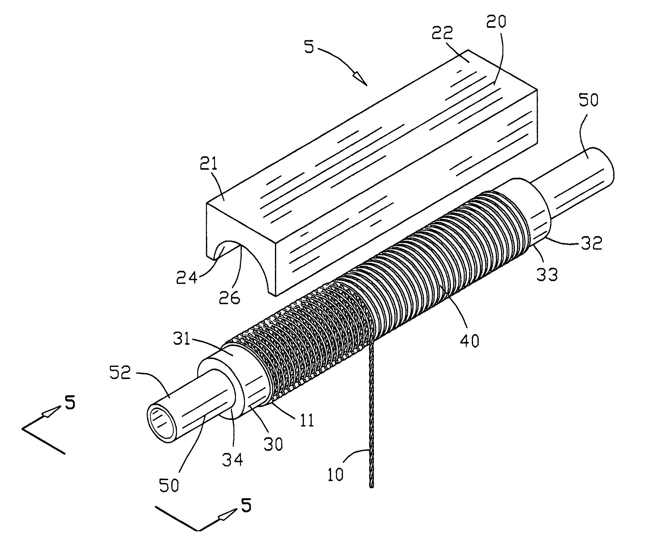
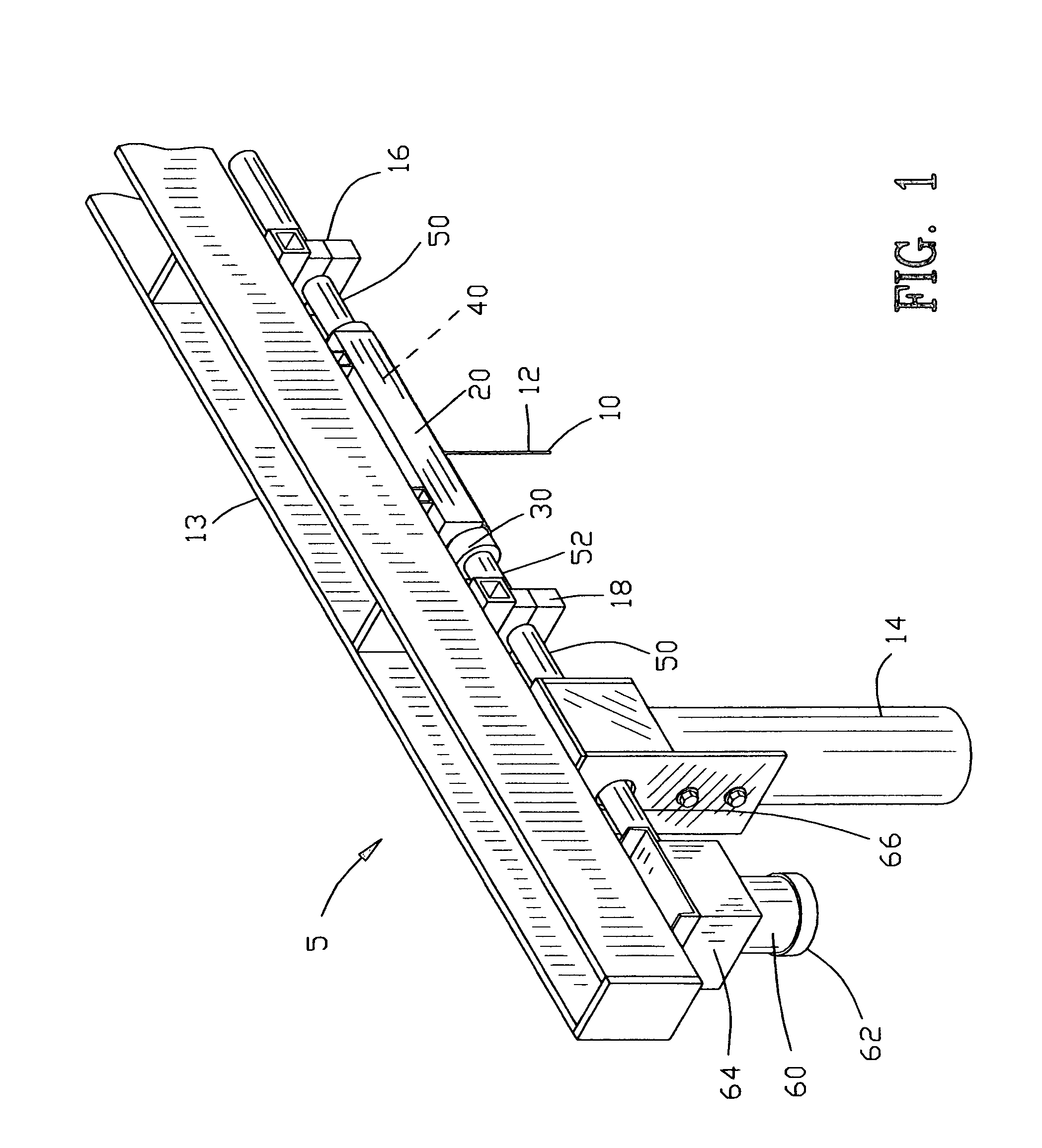
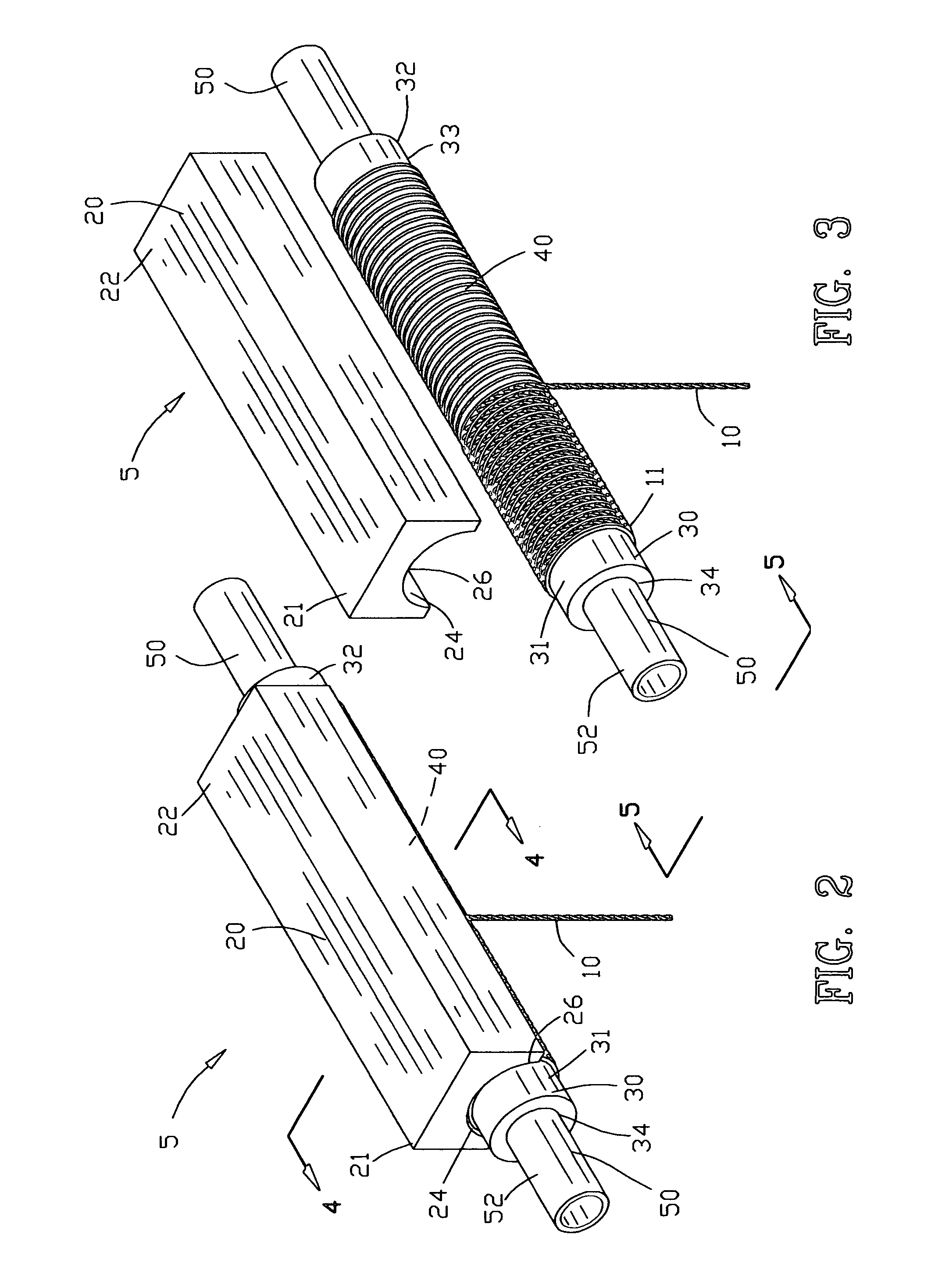
[0038]FIG. 1 illustrates a cable winder guide 5 of the present invention. In this example, the cable winder guide 5 is shown as a boat lift assembly. Although the cable winder guide 5 is shown as a boat lift assembly, it should be understood that the cable winder guide 5 may be used in other applications. The cable winder guide 5 of the present invention provides for the safe and reliable winding and unwinding of a cable 10.

[0039]The cable winder guide 5 is mounted on a horizontal support member 13 affixed to a vertical support member 14. The cable winder guide 5 comprises a cable retainer 20 and a cylindrical drum 30. The cable retainer 20 is affixed to the horizontal support member 13. A cylindrical drum 30 is affixed to a shaft 50. A helical groove 40 is defined in the cylindrical drum 30 as will be discussed in further detail hereinafter. The shaft 50 is rotatably suspended from the horizontal support member 13 by journals 16 and 18. A drive 60 is affixed to the horizontal suppo...


PUM


Abstract

A cable winder guide is disclosed comprising a cylindrical drum having a cylindrical surface with a shaft rotatably mounting the cylindrical drum. A drive is provided for rotating the cylindrical drum about the shaft. A helical groove is defined in the cylindrical surface of the drum for retrieving and releasing the cable upon rotation of the cylindrical drum. A cable retainer is disclosed for resiliently engaging the cable when the cable is located within the helical groove for maintaining the cable within the helical groove.

Description

CROSS-REFERENCE TO RELATED APPLICATIONS[0001]This application claims benefit of U.S. Patent Provisional application Ser. No. 60 / 457,224 filed Mar. 25, 2003. All subject matter set forth in provisional application Ser. No. 60 / 457,224 is hereby incorporated by reference into the present application as if fully set forth herein.BACKGROUND OF THE INVENTION[0002]1. Field of the Invention[0003]This invention relates to hoisting devices and more particularly to a cable winder guide for maintaining the cable within a helical groove on a drum.[0004]2. Background of the Invention[0005]Soon after the first successful stranded iron wire rope was developed in 1834, wire rope proved so superior to hemp rope in serviceability and cost that the use of wire rope soon became widespread in European mining and eventually throughout the rest of the world with broadening applications. Most wire ropes used today are utilized in hoisting and hauling operations. Machinery for these purposes, such as cranes,...

Claims


Application Information

Patent Timeline
IPC IPC(8): B65H27/00
CPCB66D1/36
Inventor MASSELL, GEORGEMASSELL, RICHARD
Owner DECO POWER ELEVATOR
Why Eureka
Try Eureka