Welding torch having removable handle and method of operating same

a welding torch and handle technology, applied in the field of arc welding systems, can solve the problems of limiting the ability of users to operate in tight areas, the handle is typically long or otherwise bulky, and the welding process typically generates a substantial amount of heat in the electrod

Inactive Publication Date: 2006-09-12
ILLINOIS TOOL WORKS INC
View PDF15 Cites 19 Cited by
  • Summary
  • Abstract
  • Description
  • Claims
  • Application Information

AI Technical Summary

Benefits of technology

[0006]The present technique may solve one or more of the needs outlined above. According to one aspect of the present technique, a welding torch is provided. The welding torch has a torch body that is adapted to receive a welding electrode. A collet and collet body may be used to secure the electrode to the torch body. The welding torch has a handle that is securable to the torch body, but which may be removed from the torch body. The welding torch may be operated with the handle removed. The welding torch is adapted to prevent arcing from the torch body to a surrounding surface when the handle is removed. The welding torch also may have a cable that is adapted to convey gas and electricity that is affixed to the torch body. The torch body may have an electrical connector disposed within the torch body for connection to the cable operable to convey gas and electricity. The cable and torch may also be adapted to provide cooling water to the torch body. The torch body may also be flexible.

Problems solved by technology

Furthermore, the TIG welding process typically generates a substantial amount of heat in the electrode.
However, the handle typically is long or otherwise bulky and limits the ability of a user to operate in tight areas.
However, if the handle is removed, conductive metal portions of the welding torch are exposed, such as the connectors used to connect the torch body to the welding cable, increasing the possibility of an arc being produced between the welding torch and an adjacent structure, or the user.

Method used


Image

  • Welding torch having removable handle and method of operating same
  • Welding torch having removable handle and method of operating same
  • Welding torch having removable handle and method of operating same

Examples


Embodiment Construction

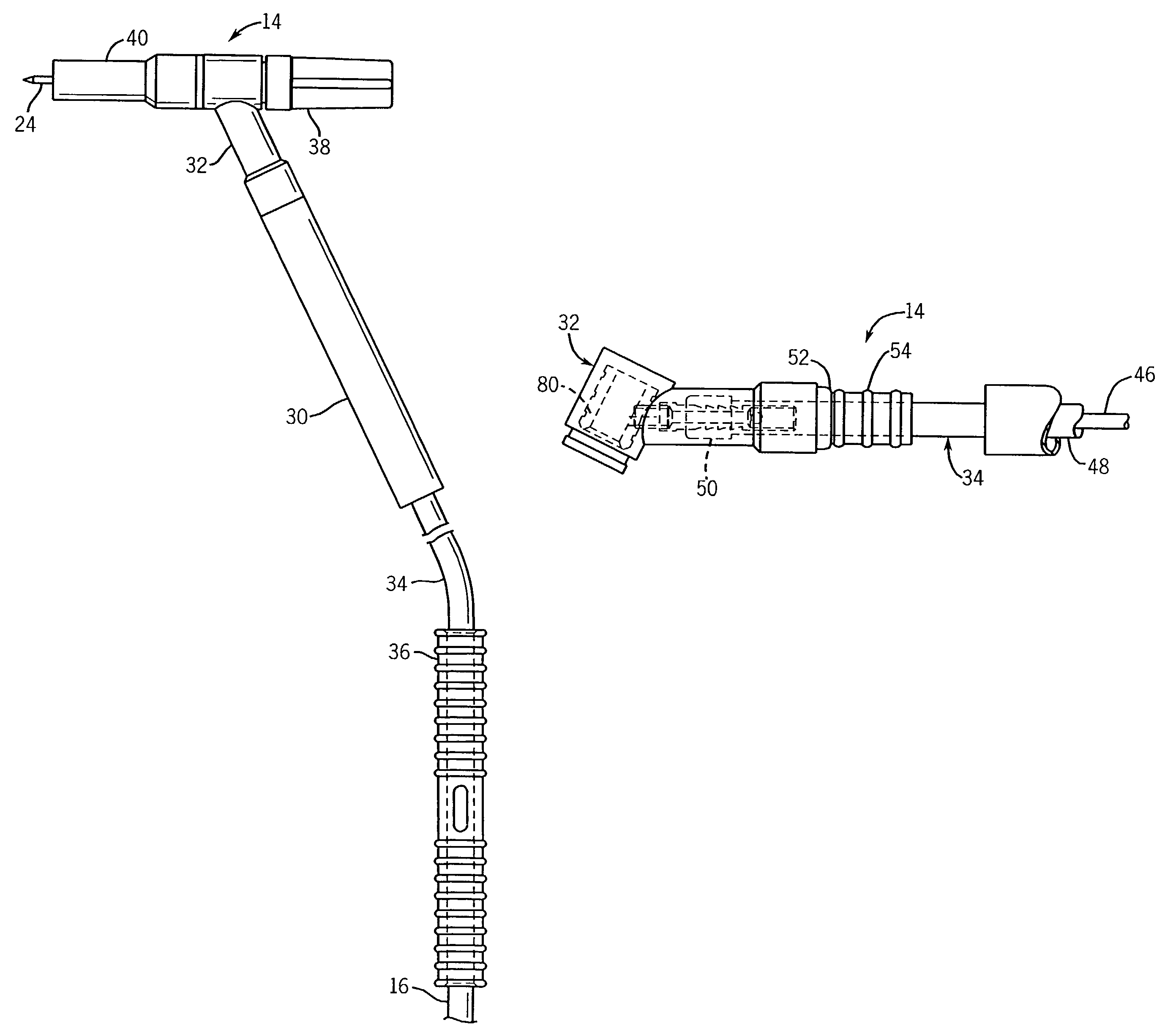
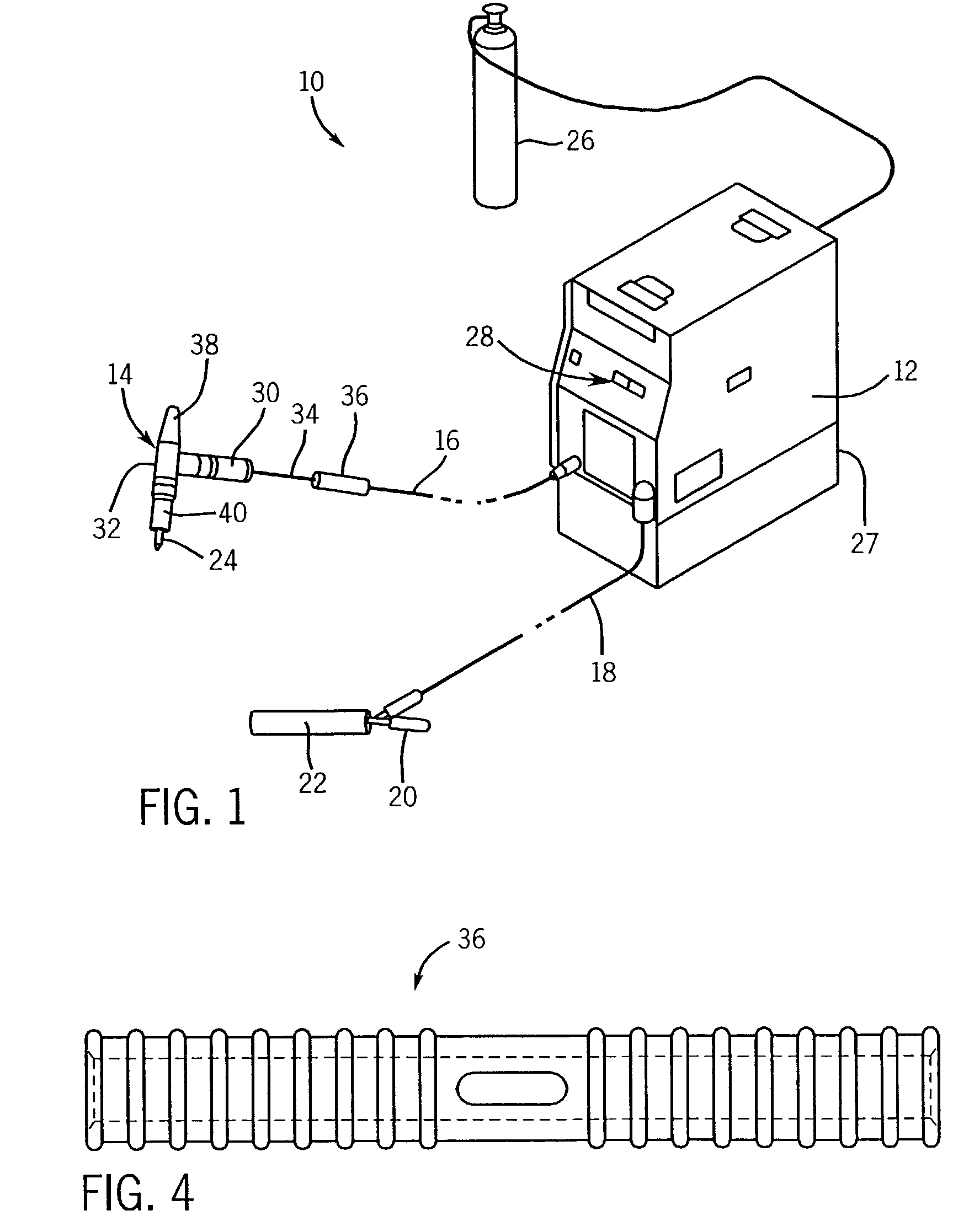
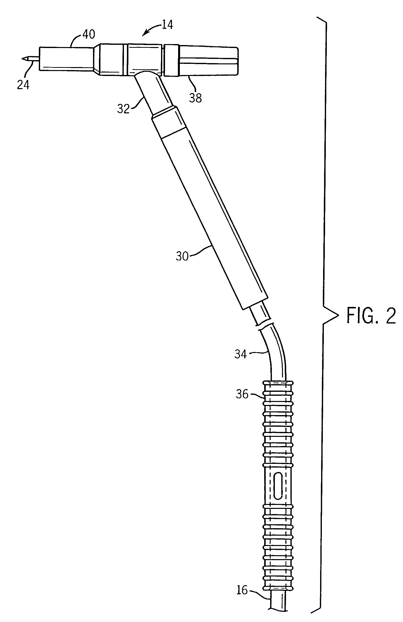
[0018]Referring generally to FIG. 1, a portable TIG welding system is illustrated, as represented generally by reference numeral 10. However, the techniques provided below may be used with other types of welding systems. The TIG welding system 10 comprises a power supply 12, a TIG welding torch 14, a welding cable 16, and a return cable 18. The power supply 12 may be a constant voltage AC, DC, a combination AC / DC source, or some other type of power supply. The welding cable 16 electrically couples the welding torch 14 to one terminal of the power supply 12. The return cable 18 is coupled to a second terminal of the power supply 12. In the illustrated embodiment, the return cable 18 has a clamp 20 that is adapted to secure and electrically couple the return cable 18 to a workpiece 22 to be welded. The welding torch 14 is adapted to receive an electrode 24. When the electrode 24 comes in close proximity to or touches the material 22 to be welded, an electric circuit is completed from ...


PUM

PropertyMeasurementUnit
flexibleaaaaaaaaaa
electrically insulatingaaaaaaaaaa
electricallyaaaaaaaaaa

Abstract

A welding torch having a torch body that is adapted to receive a welding electrode. A collet and collet body, or other mechanism, may be used to secure the electrode to the torch body. The welding torch has a handle that is securable to the torch body, but which may be selectively removed from the torch body. The welding torch may be operated with the handle removed. The welding torch is adapted to prevent arcing from the torch body to a surrounding surface when the handle is removed. The welding torch also may have a cable that is adapted to convey gas and electricity that is affixed to the torch body. The torch body may have an electrical connector disposed within the torch body for connection to the cable operable to convey gas and electricity. The cable and torch may also be adapted to provide cooling water to the torch body. The torch body may also be flexible.

Description

BACKGROUND OF THE INVENTION[0001]The present invention relates generally to the field of arc welding systems, and more particularly to an arc welding torch that is adapted for operation with a removable handle.[0002]TIG (Tungsten Inert Gas) welding (also known as gas tungsten arc welding, GTAW, or HELIARC) is a type of arc welding process in which an electric arc is maintained between a cylindrical metal electrode and a metal object. The heat generated by the arc produces localized melting of the metal object. The electrode, typically tungsten, is secured to a torch to enable a user to direct the electrode and establish the point of contact between the electrode and the object. TIG welding may be performed with or without the addition of a filler metal. Typically, the weld puddle and the area surrounding the weld puddle are protected from the atmosphere by an inert gas. The inert gas prevents rapid oxidation of the weld and the surrounding metal.[0003]The electricity for the welding...

Claims


Application Information

Patent Timeline
Patent Type & Authority Patents(United States)
IPC IPC(8): B23K9/00B23K9/28
CPCB23K9/285
Inventor SAMLER, GARY R.
Owner ILLINOIS TOOL WORKS INC
Why Eureka
Try Eureka