FinFET with low gate capacitance and low extrinsic resistance

a technology of finfets and gate capacitance, applied in the field of microelectronic devices, can solve the problems of gate capacitance, device performance degradation,

Active Publication Date: 2006-09-12
MICROSOFT TECH LICENSING LLC
View PDF7 Cites 76 Cited by
  • Summary
  • Abstract
  • Description
  • Claims
  • Application Information

AI Technical Summary

Benefits of technology

[0011]As a result of the embodiments of the invention, FinFETs with lower gate capacitance, lower drain and source capacitance and reduce extrinsic resistance can be achieved. Improved circuit performance, reduced switching time, and decreased power consumptions comprise some of the advantages which flow from the embodiments of the invention. Improved radio-frequency and analog circuit operation are also enabled by both the reduced drain-to-gate capacitance and the reduced extrinsic resistance advantages of the inventive embodiments.

Problems solved by technology

Thin-silicon-body field effect transistors (FETs) present a challenge to providing a low-resistance conduction path from the contacts to the source and drain electrodes to the intrinsic channel region in between the source and drain electrodes.
However, if this expansion (flair out) is made more than several body thicknesses away from the gate, then the added resistance from the relatively long line of thin silicon in the extrinsic region adds substantial extrinsic resistance to the device, thereby degrading device performance.
On the other hand, if the expansion (flair out) is made relatively near the gate electrode, then the capacitance between the wide extrinsic region and the gate becomes large thereby increasing gate capacitance, which then causes degradation in device performance.
For example, outer-fringe gate-drain capacitance (Cof) can be high in FinFET devices, which degrades device performance.
While these solutions have provided a possible solution to the low gate capacitance and low extrinsic resistance trade-off, the actual design and fabrication of such structures capable of achieving this trade-off has been extremely difficult and quite expensive.
However, until now no known adequate solution has been designed and fabricated.

Method used


Image

  • FinFET with low gate capacitance and low extrinsic resistance
  • FinFET with low gate capacitance and low extrinsic resistance
  • FinFET with low gate capacitance and low extrinsic resistance

Examples


Embodiment Construction

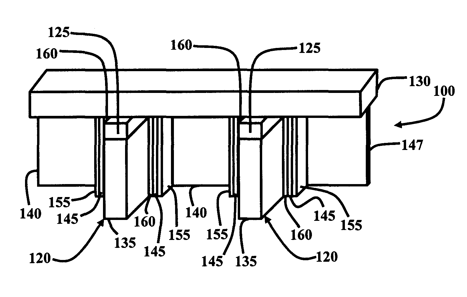
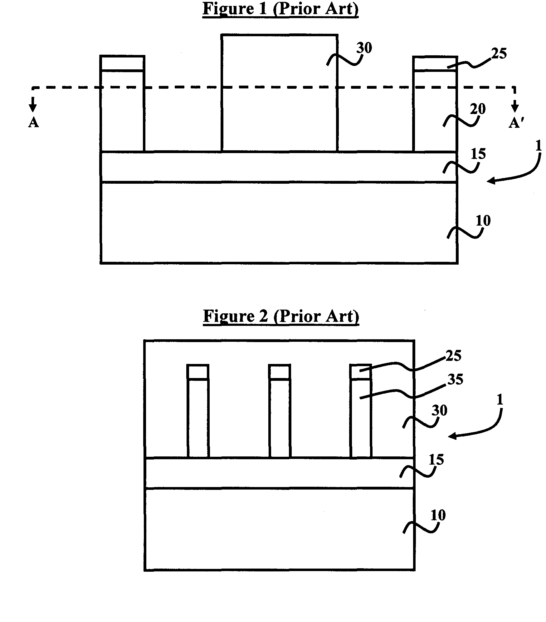
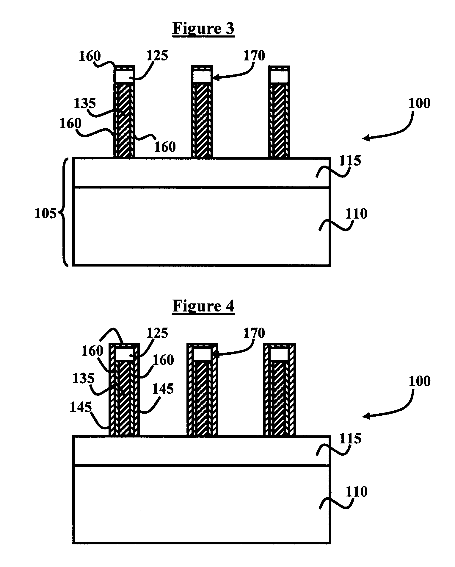
[0028]The embodiments of the invention and the various features and advantageous details thereof are explained more fully with reference to the non-limiting embodiments that are illustrated in the accompanying drawings and detailed in the following description. It should be noted that the features illustrated in the drawings are not necessarily drawn to scale. Descriptions of well-known components and processing techniques are omitted so as to not unnecessarily obscure the embodiments of the invention. The examples used herein are intended merely to facilitate an understanding of ways in which the embodiments of the invention may be practiced and to further enable those of skill in the art to practice the embodiments of the invention. Accordingly, the examples should not be construed as limiting the scope of the embodiments of the invention.

[0029]As mentioned, there remains a need for a novel method and structure, which provides superior FinFET device performance while simultaneousl...


PUM


Abstract

A FinFET device and a method of lowering a gate capacitance and extrinsic resistance in a field effect transistor, wherein the method comprises forming an isolation layer comprising a BOX layer over a substrate, configuring source / drain regions above the isolation layer, forming a fin structure over the isolation layer, configuring a first gate electrode adjacent to the fin structure, disposing a gate insulator between the first gate electrode and the fin structure, positioning a second gate electrode transverse to the first gate electrode, and depositing a third gate electrode on the fin structure, the first gate electrode, and the second gate electrode, wherein the isolation layer is formed beneath the insulator, the first gate electrode, and the fin structure. The method further comprises sandwiching the second gate electrode with a dielectric material. The fin structure is formed by depositing an oxide layer over a silicon layer.

Description

BACKGROUND OF THE INVENTION[0001]1. Field of the Invention[0002]The invention generally relates to microelectronic devices, and more particularly to the design and manufacturing of FinFET devices having improved performance characteristics.[0003]2. Description of the Related Art[0004]Thin-silicon-body field effect transistors (FETs) present a challenge to providing a low-resistance conduction path from the contacts to the source and drain electrodes to the intrinsic channel region in between the source and drain electrodes. Typically, one must expand (flair out) the thickness of the body by some distance beyond its egress from beneath the gate to provide adequate electrical conduction. However, if this expansion (flair out) is made more than several body thicknesses away from the gate, then the added resistance from the relatively long line of thin silicon in the extrinsic region adds substantial extrinsic resistance to the device, thereby degrading device performance.[0005]On the o...

Claims


Application Information

Patent Timeline
Patent Type & Authority Patents(United States)
IPC IPC(8): H01L29/76H01L21/332H01L21/335
CPCH01L29/42384H01L29/785H01L29/66795Y10S257/90
Inventor ANDERSON, BRENT A.BRYANT, ANDRESNOWAK, EDWARD J.
Owner MICROSOFT TECH LICENSING LLC
Why Eureka
Try Eureka