Switchable tuneable bandpass filter with optimized frequency response

a bandpass filter and tuning technology, applied in continuous tuning, discontnuous tuning with seperate pretuned circuits, television systems, etc., can solve the problem of relatively large level differences over the two frequency ranges, the coupling elements ck and rk can be set optimally, and the tuning range can be restricted. achieve uniform gain response, without significantly increasing the overall outlay

Inactive Publication Date: 2006-09-12
THOMSON LICENSING SA
View PDF15 Cites 7 Cited by
  • Summary
  • Abstract
  • Description
  • Claims
  • Application Information

AI Technical Summary

Benefits of technology

[0013]In a second switch position, a second primary resonant circuit comprises the first variable capacitance and the first inductance of the first primary resonant circuit described above. The now closed switch connects the first inductance to a second common reference point inductance. A second secondary resonant circuit, comprising a fourth inductance and a third variable capacitance, is connected to the second common reference point inductance. The output of the second secondary resonant circuit is connected to the mixer by means of second coupling elements in a known manner. Since the second common reference point inductance, which takes effect when the switch is closed, is lower in value than the remaining second inductance of the first primary resonant circuit in the first switch position, the elements connected to the circuit via the remaining second inductance can be disregarded. The values of the inductances differ by the factor three, for example, other expedient ratios also being possible. A second switch for disconnecting the unrequired part of the circuit is thus superfluous.
[0014]The invention advantageously makes it possible to achieve a uniform gain response over the two switchable frequency ranges without significantly increasing the overall outlay.

Problems solved by technology

The properties of components of the kind usually used in receivers lead to a limitation of the tuning range that can be achieved.
The advantage of the lowest outlay compared with the first two concepts is opposed by the disadvantage that the coupling elements CK and RK can be set optimally only for one range.
As a result, relatively large level differences can occur over the two frequency ranges and impair the properties of a tuner.
In order to avoid this effect, although it is possible for the coupling elements to be configured in switchable fashion, this nevertheless results in an increase in the circuitry outlay again.

Method used


Image

  • Switchable tuneable bandpass filter with optimized frequency response
  • Switchable tuneable bandpass filter with optimized frequency response
  • Switchable tuneable bandpass filter with optimized frequency response

Examples


Embodiment Construction

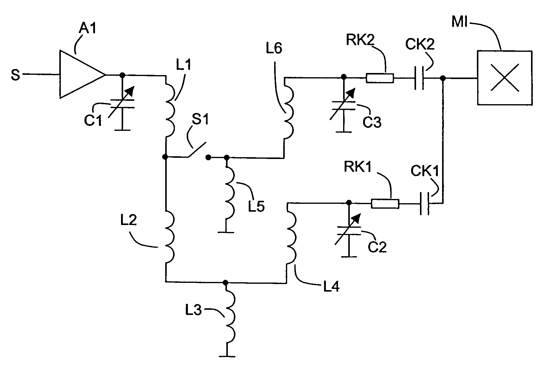
[0026]FIG. 5 shows a diagrammatic illustration of a simplified practical embodiment of the switchable tuneable bandpass filter according to the invention. An input signal S passes from an antenna (not shown in the figure) via an input filter (likewise not illustrated in the figure) to an input amplifier A1. In a first switch position of a switch S1, the switch S1 is open. The signal passes from the output of the input amplifier A1 to a first primary resonant circuit. The first primary resonant circuit is formed from a variable capacitance C1, the series circuit formed by two inductances L1 and L2 and also an inductance L3. In this case, the inductance L3 is a common reference point inductance for the first primary resonant circuit and a first secondary resonant circuit. In this switched position of the switch S1, the first secondary resonant circuit is formed by the inductance L4 and the variable capacitance C2. In order to obtain the desired property of the bandpass filter, the ind...


PUM


Abstract

In a receiver, provision is made of a tuneable switchable bandpass filter comprising a primary resonant circuit and a first secondary resonant circuit. A second secondary resonant circuit can be switched into a part of the first primary resonant circuit, thereby producing a second primary resonant circuit. By virtue of the embodiment of the primary resonant circuit, the bandpass filter is switchable in terms of frequency range with little outlay on circuitry and, on account of the individual embodiment of a first and second secondary resonant circuit with individual coupling elements, can be optimized with regard to a constant amplitude response.

Description

[0001]This application claims the benefit under 35 U.S.C. § 119 (a) of German patent application No. 10300892.6 filed Jan. 13, 2003.FIELD OF THE INVENTION[0002]The invention relates to a switchable tuneable bandpass filter in accordance with the preamble of the first claim.BACKGROUND OF THE INVENTION[0003]In receivers which have to be tuned over a wide frequency range, such as e.g. the radio-frequency receivers in radio or television tuners, the reception range is divided into a plurality of subranges.[0004]Present-day customary television receivers have to be able to receive signals in a range from 48 MHz to 860 MHz. The properties of components of the kind usually used in receivers lead to a limitation of the tuning range that can be achieved. The entire frequency range that can be achieved by a television receiver is therefore divided e.g. into three ranges. In this case, a first range extends from 48 to 150 MHz, a second range extends from 150 to 430 MHz, and a third range exten...

Claims


Application Information

Patent Timeline
Patent Type & Authority Patents(United States)
IPC IPC(8): H03H7/00H03J5/00H03H7/12H03F1/34H03F1/36H03F1/38H03F3/04H03F3/191H03H7/01H03H9/46H03H15/00H03J3/00H03J5/24H04B1/00H04B1/16H04N5/44
CPCH03H7/0161H03J5/244H03H2250/00H03H2210/015H03H9/46H03J7/00
Inventor SELZ, ALFRED
Owner THOMSON LICENSING SA
Why Eureka
Try Eureka