
Rasterizer edge function optimizations

a rasterizer and edge function technology, applied in the field of 3d graphics processing, can solve the problems of large data manipulation to be done, large memory bandwidth, and large geometry to be added,

Inactive Publication Date: 2006-09-12
XUESHAN TECH INC
View PDF1 Cites 2 Cited by
  • Summary
  • Abstract
  • Description
  • Claims
  • Application Information

AI Technical Summary

Benefits of technology

[0011]There are different ways to add complexity to a 3D scene. Creating more and more detailed models, consisting of a greater number of polygons, is one way to add visual interest to a scene. However, adding polygons necessitates paying the price of having to manipulate more geometry. 3D systems have what is known as a “polygon budget,” an approximate number of polygons that can be manipulated without unacceptable performance degradation. In general, fewer polygons yield higher frame rates.
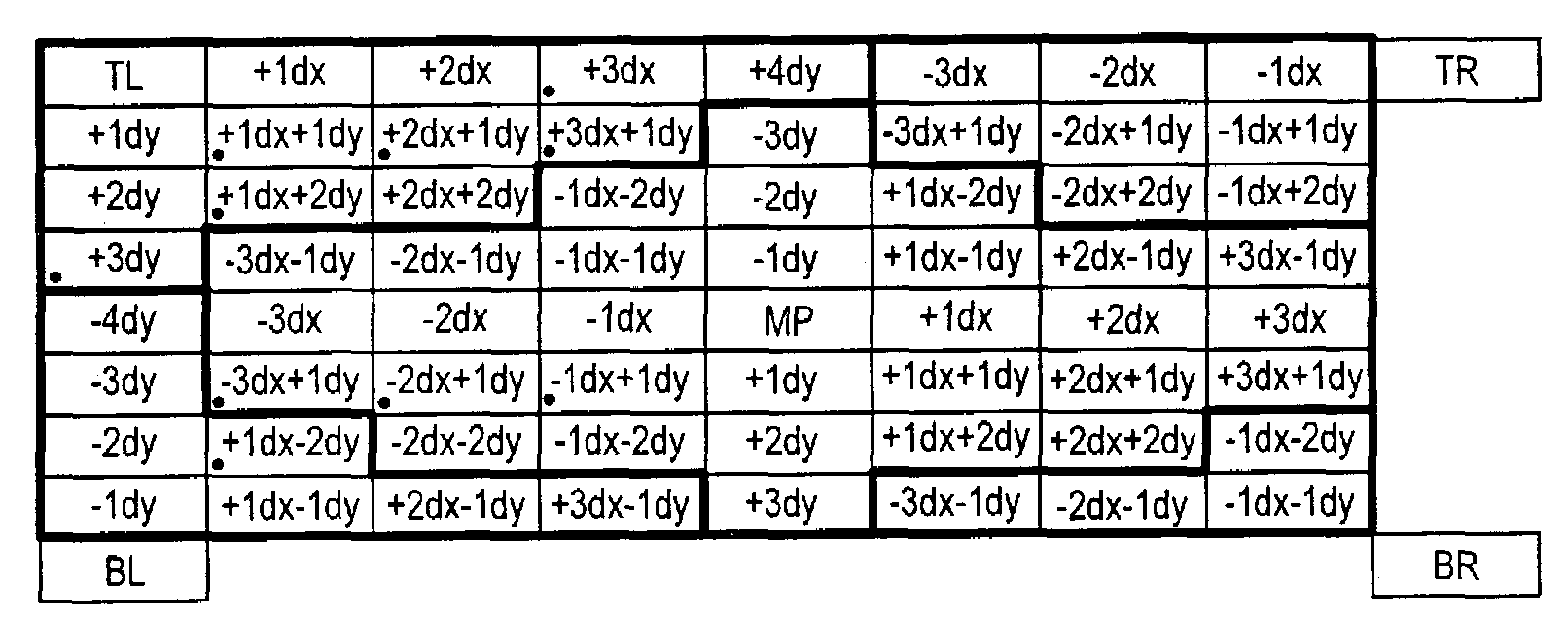
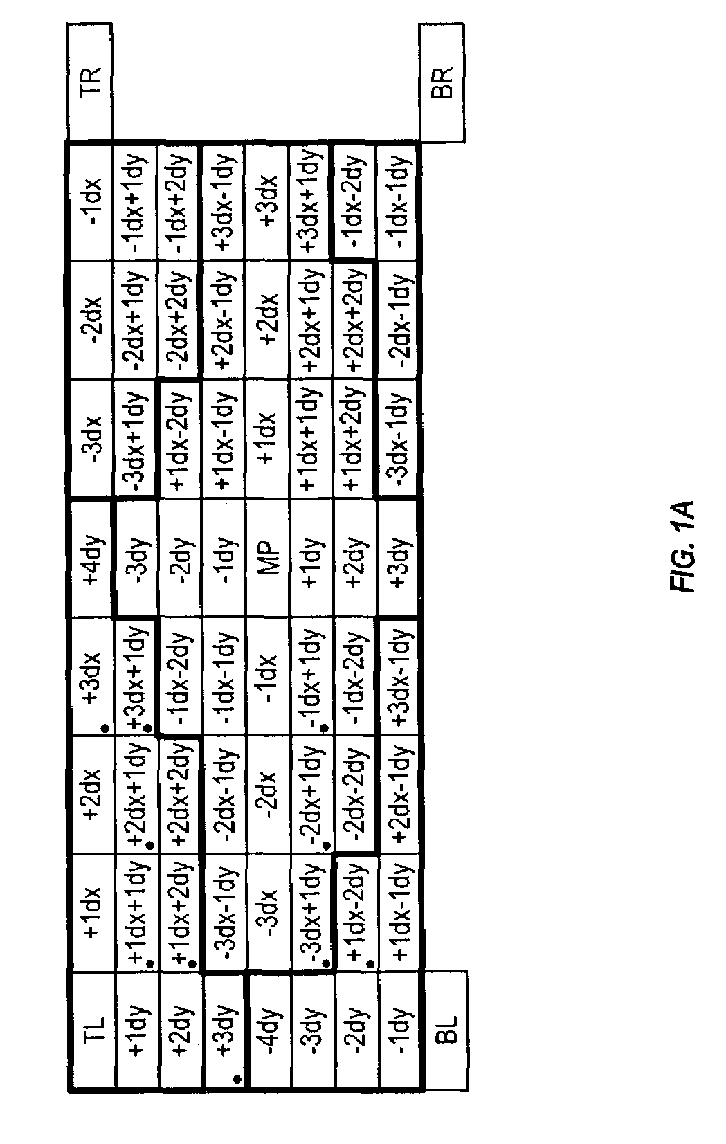
[0016]The present application describes a set of techniques for rapidly computing a function (such as a half-plane membership test) for patches of pixels (more generally, for points on a grid). By using an inheritance relation to carry forward values already computed at patch boundaries, and by using symmetry relations to shift and / or complement offset value for pixels within a patch, the computational load for each successive patch is minimized. This is particularly advantageous for rapidly testing primitive membership of successive patches of pixels.
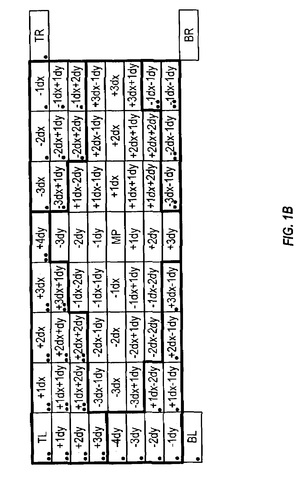
[0021]FIG. 1B shows how a reduced set of offset values are combined with incremental reference points, in a sample embodiment, to permit rapid calculation of an edge function for all pixels in a patch.

Problems solved by technology

However, even after these transformations and extensive calculations have been done, there is still a large amount of data manipulation to be done: the correct values for EACH PIXEL of the transformed polygons must be derived from the two-dimensional representation.
The most challenging 3D graphics applications are dynamic rather than static.
However, adding polygons necessitates paying the price of having to manipulate more geometry.
Achieving an adequately high rate of texturing and fill operations requires a very large memory bandwidth.

Method used


Image

  • Rasterizer edge function optimizations
  • Rasterizer edge function optimizations
  • Rasterizer edge function optimizations

Examples


computer embodiment

[0062]FIG. 4 shows a complete computer system, incorporating the graphics accelerator of FIG. 3, and including in this example: user input devices (e.g. keyboard 435 and mouse 440); at least one microprocessor 425 which is operatively connected to receive inputs from the input devices, across e.g. a system bus 431, through an interface manager chip 430 which provides an interface to the various ports and registers. The microprocessor interfaces to the system bus through e.g. a bridge controller 427. Memory (e.g. flash or non-volatile memory 455, RAM 460, and BIOS 453) is accessible by the microprocessor. a data output device (e.g. display 450 and video display adapter card 445, which includes a graphics accelerator subsystem 451) which is connected to output data generated by the microprocessor 425; and a mass storage disk drive 470 which is read-write accessible, through an interface unit 465, by the microprocessor 425. Optionally, of course, many other components can be included, ...


PUM


Abstract

A set of techniques for rapidly computing a half-plane membership test for successive patches of pixels. By using an inheritance relation to carry forward values already computed at patch boundaries, the computational load for each successive patch is minimized. In a sample embodiment, just one interior point and one new boundary point are computed for each new patch of 64 pixels. Each of the 64 pixels can be described by an offset from one of the 5 reference points (i.e. the one interior point, the one newly computed boundary point, and 3 previously computed boundary points). By exploiting shift and complement relations, only a small number of offsets need to be independently computed (only 10 in this example). Since membership is determined merely by the sign of the relevant half-plane functions being computed, a simple compare between the half-plane function at the reference point and the half-plane function for the relevant offset suffices to evaluate the function's sign for that particular pixel.

Description

CROSS-REFERENCE TO OTHER APPLICATION[0001]This application claims priority from 60 / 267,265 filed Feb. 8, 2001, which is hereby incorporated by reference.BACKGROUND AND SUMMARY OF THE INVENTION[0002]The present invention relates to 3D graphics processing, and particularly to rasterization.BACKGROUND3D Computer Graphics[0003]One of the driving features in the performance of most single-user computers is computer graphics. This is particularly important in computer games and workstations, but is generally very important across the personal computer market.[0004]For some years the most critical area of graphics development has been in three-dimensional (“3D”) graphics. The peculiar demands of 3D graphics are driven by the need to present a realistic view, on a computer monitor, of a three-dimensional scene. The pattern written onto the two-dimensional screen must therefore be derived from the three-dimensional geometries in such a way that the user can easily “see” the three-dimensional...

Claims


Application Information

Patent Timeline
IPC IPC(8): G06T15/00G06T15/20
CPCG06T15/20G06T2200/28
Inventor LAWS, PHILIP R.WORTHINGTON, JON
Owner XUESHAN TECH INC
Learn More